Leakage disengaging deivce of earth leakage breaker

An earth leakage circuit breaker and trip device technology, applied in circuit breaker parts, circuits, switchgear and other directions, can solve the problems such as the difficulty of effectively utilizing the space for circuit breakers to store, and the difficulty in assembling the device as a whole in a compact manner.

Active Publication Date: 2008-05-07
FUJI ELECTRIC FA COMPONENTS & SYST CO LTD
View PDF1 Cites 10 Cited by
  • Summary
  • Abstract
  • Description
  • Claims
  • Application Information

AI Technical Summary

Problems solved by technology

[0009] If the existing leakage tripping unit shown in FIG. 9 is reconsidered from the above-mentioned point of view, then for the structure in which the tripping coil 8, the tripping actuator 9, and the leakage display button 10 are assembled on the assembly base 12 as independent components, And the tripping coil 8 and the tripping actuator 9 are arranged along the horizontal axis direction. Since the pop-up type leakage display button 10 is arranged along the vertical axis direction, etc., the orientation of the components is different, and it is difficult to make the whole device compact. It is difficult to effectively use the space in the main case of the circuit breaker due to the large size

Method used


Image

  • Leakage disengaging deivce of earth leakage breaker
  • Leakage disengaging deivce of earth leakage breaker
  • Leakage disengaging deivce of earth leakage breaker

Examples


Embodiment 1

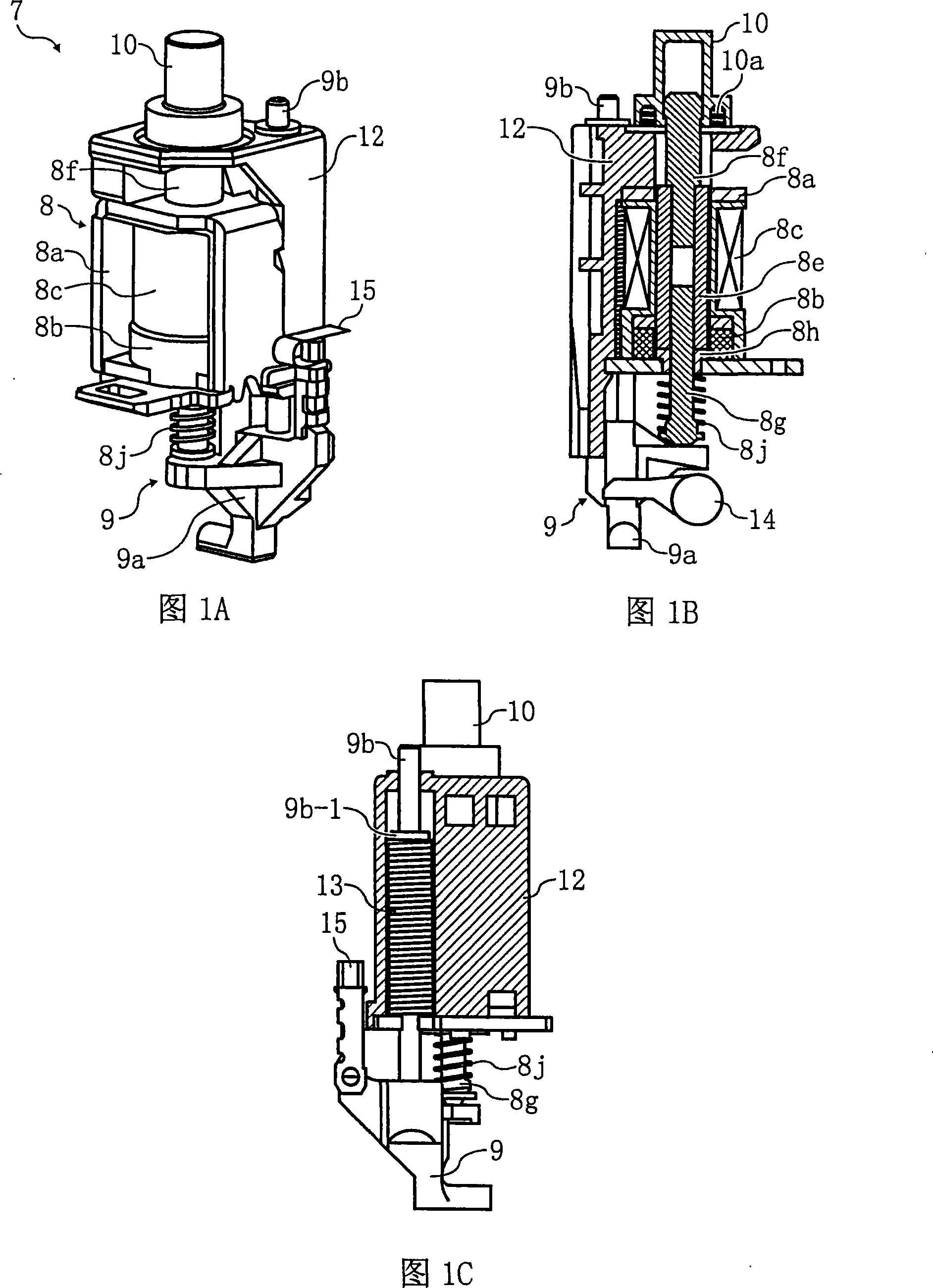
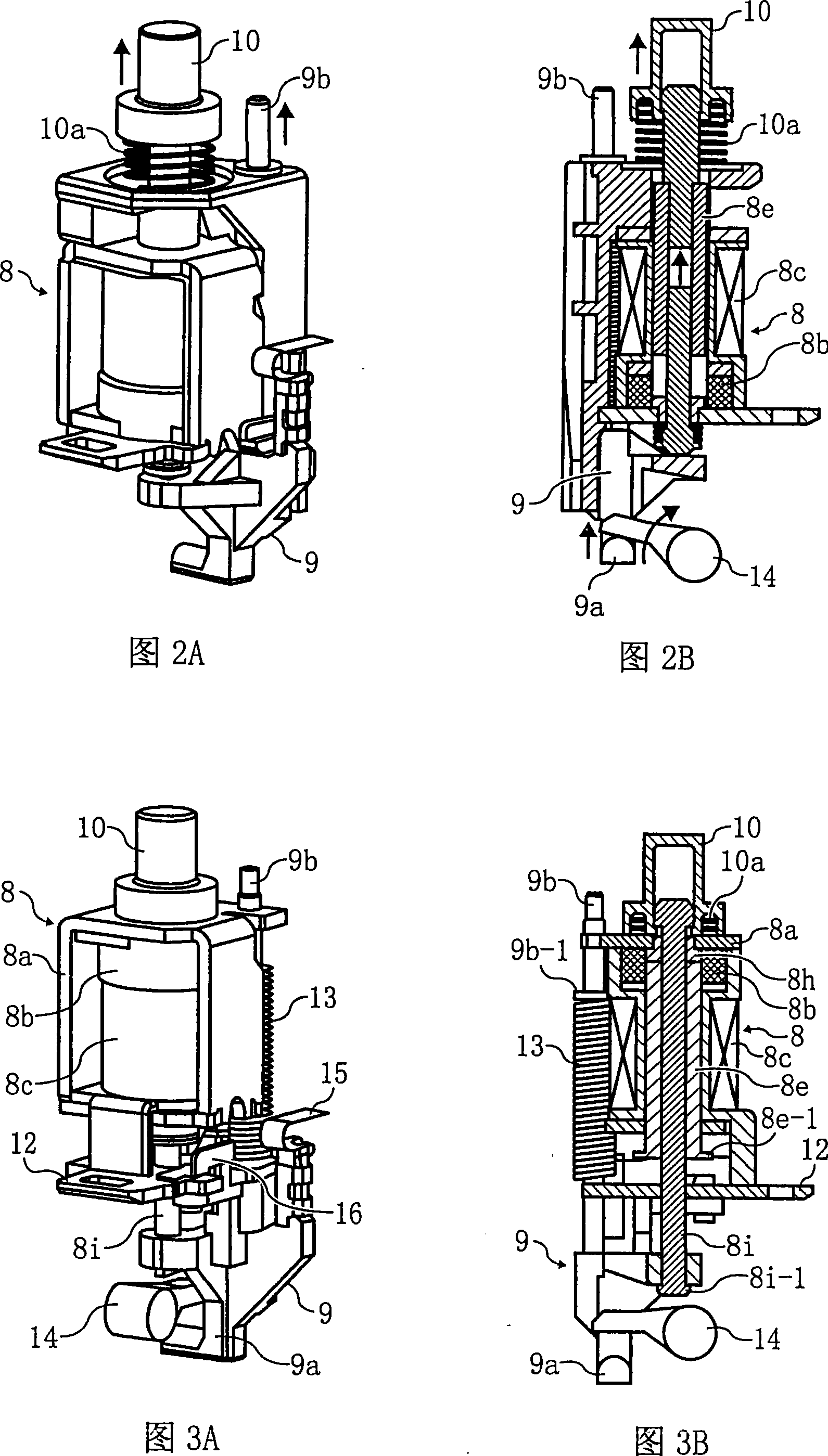
[0039] 1A to 1C and 2A to 2B to describe the structure and operation of the embodiment according to the technical solutions (1) to (3) of the present invention.

[0040] The leakage tripping device of the illustrated embodiment takes the leakage trip coil 8 as the core component, and assembles a trip actuator 9 and a pop-up type leakage display button 10 on it to form a unit structure, which is different from the prior art shown in FIG. 9 The structure is basically the same, however, in order to realize the miniaturization of the whole device, each part is connected and arranged as follows.

[0041] First, the leakage tripping coil 8 is provided with a permanent magnet 8b, a demagnetizing coil 8c wound on a bobbin, and a movable iron core 8e and a fixed iron core inside a yoke 8a composed of an inverted U-shaped leg piece and a bottom piece. The magnetic holding type electromagnet 8h is arranged on the assembly base 12 so that the permanent magnet 8b is arranged on the lower s...

Embodiment 2

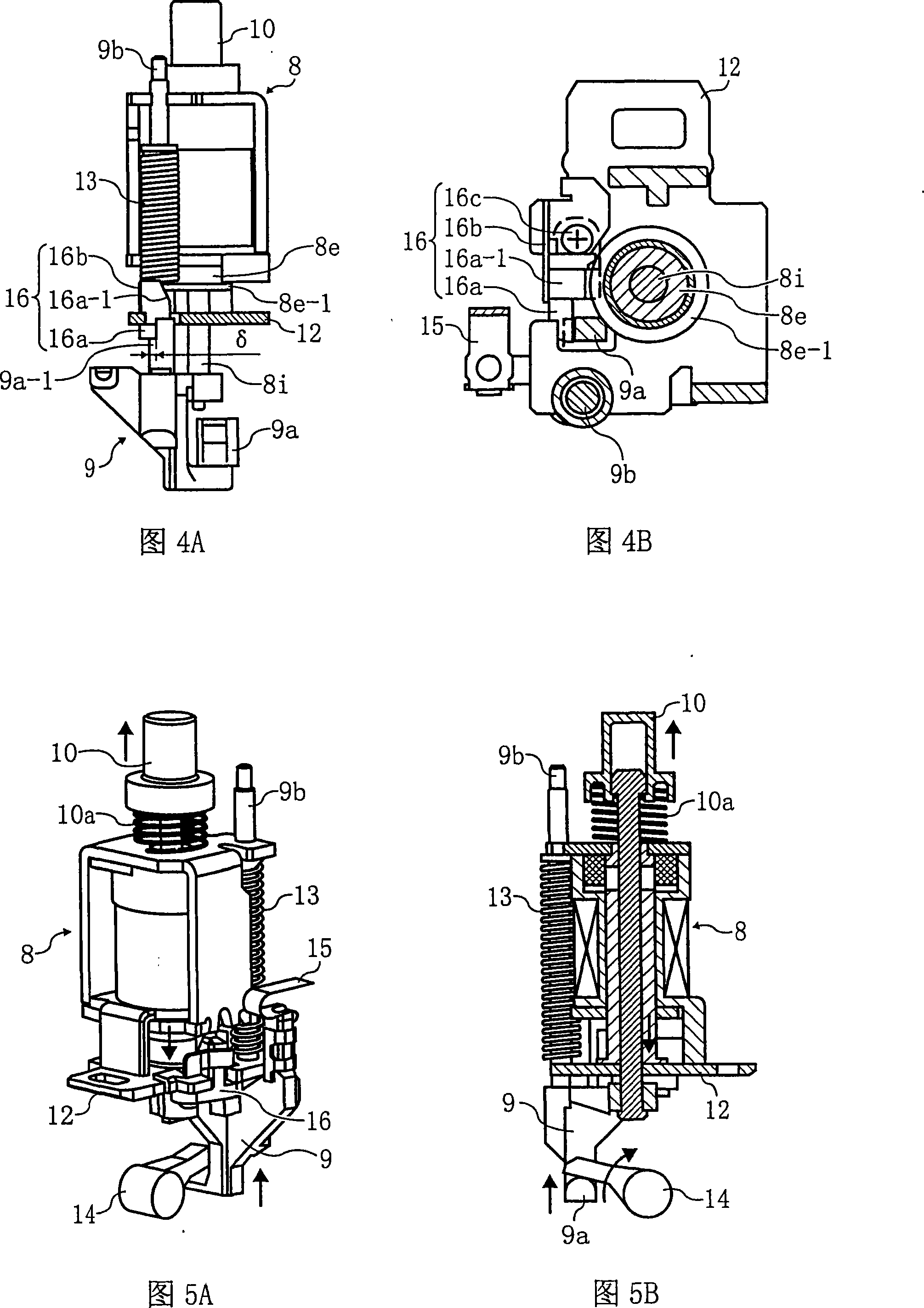
[0049] Next, an improved embodiment corresponding to technical solutions (4)-(5) of the present invention, which further develops the structure of the above-mentioned embodiment 1, will be described with reference to FIGS. 3A to 6B.

[0050] In this embodiment, the configuration of the leakage tripping coil 8, the tripping actuator 9, and the leakage display button 10 is the same as that of the above-mentioned embodiment 1, but the leakage tripping coil 8, and the connection between the leakage tripping coil 8 and the tripping actuator 9 The structure is different.

[0051] That is, on the yoke 8a, the permanent magnet 8b, the demagnetization coil 8c, the movable iron core 8e, and the trip coil 8 of the fixed iron core 8h are combined. - 1C) On the contrary, the permanent magnet 8b is arranged on the upper side of the demagnetization coil 8c and mounted on the assembly base 12 . In addition, a plunger shaft 8i made of a non-magnetic material is loosely fitted into a cylindric...


PUM


Abstract

The invention relates to a creepage disengaging device for a creepage breaker, with a subject of improving the connection and configuration structure of the components of the creepage disengaging device loaded in the creepage breaker so as to achieve a small size and the compactness. The solution scheme is as below: in the creepage disengaging device which is provided with a creepage tripping coil (8), a tripping actuator (9) connected with a plunger of the creepage tripping coil and an upward bounced creepage display button (10), the creepage tripping coil is a magnetism maintaining electromagnet which has a magnetic yoke (8a) provided with a permanent magnet (8b) and a degaussing coil (8c). The electromagnet is arranged on an ordinate axis and has one side at the upper part connected with the creepage display button through the plunger of the creepage tripping coil. Besides, the tripping actuator which moves upwards and downwards under a force exerted upwards by a tripping spring is arranged on one side of the lower part of the tripping coil.

Description

technical field [0001] The invention relates to an assembly structure of a leakage tripping device mounted on a leakage circuit breaker suitable for a low-voltage power distribution system. Background technique [0002] The circuit of the above earth leakage circuit breaker is shown in FIG. 7 . In this figure, symbol 1 represents the main circuit; 2 represents the contact point of the main circuit; 3 represents the zero-phase converter using the main circuit 1 as the primary conductor; 4 represents the leakage detection circuit, which is used for the secondary The output detects the ground current flowing through the main circuit 1; 5 indicates the opening and closing mechanism of the main circuit contact 2; 6 indicates the opening and closing operating handle; Disconnected; 8 represents the tripping coil; 9 represents the actuator, which accepts the action of the tripping coil 8 to disconnect the opening and closing mechanism 5; 10 represents the leakage display button, wh...

Claims


Application Information

Patent Timeline
Patent Type & Authority Applications(China)
IPC IPC(8): H01H83/02H01H71/32H01H71/04
CPCH01H9/20H01H33/46H01H71/123H01H73/18H02B11/133
Inventor 青木忠久朝日信夫
Owner FUJI ELECTRIC FA COMPONENTS & SYST CO LTD
Why Eureka
Try Eureka