Method for jointing metal sheets and sander

A joining method and technology of metal plates, applied in the field of joining, can solve problems such as impact deformation, exposed appearance of screws, residual stress, etc., and achieve the effect of preventing the attenuation of magnetic force

Inactive Publication Date: 2008-07-30
川真田博康
View PDF3 Cites 7 Cited by
  • Summary
  • Abstract
  • Description
  • Claims
  • Application Information

AI Technical Summary

Problems solved by technology

[0003]However, the following problems will occur: when the metal plate is thermally deformed during welding, residual stress will be generated; during riveting, impact deformation will be generated around the riveting hole due to instantaneous point pressure and residual stress, and instability due to joint accuracy or post-joint deformation; in addition, the screw insertion work during screw fixing is complicated; and in either case, welding marks or rivets and screws are exposed. question
[0024] However, since the above-mentioned belt grinder supports the pad by hand for operation, the following problems arise: the work load is large and it is difficult to perform long-term operation, and at the same time , the pad body is flexible, so in order to maintain the desired curvature of the pad body, the fingers need to perform subtle operations, which increases the burden on the fingers, and the operation requires skilled operation

Method used


Image

  • Method for jointing metal sheets and sander
  • Method for jointing metal sheets and sander
  • Method for jointing metal sheets and sander

Examples


Embodiment Construction

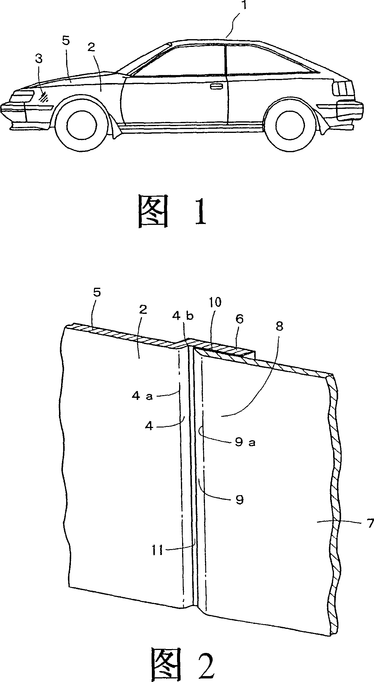
[0137] Below, the present invention will be described for the illustrated embodiment of the method of repairing the damaged part of the automobile body; among Fig. One part has a damaged part 3 .

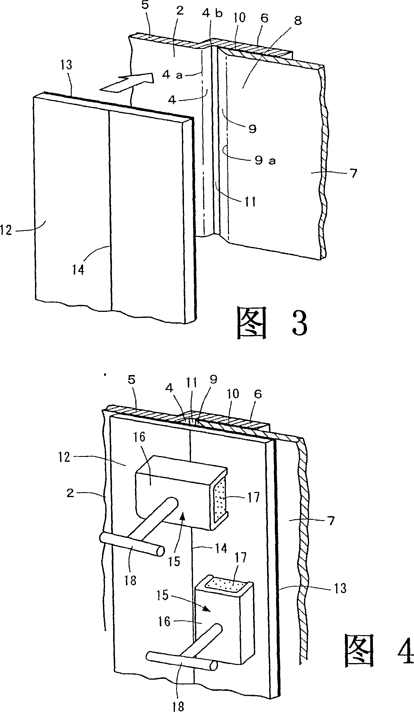
[0138] When repairing the above-mentioned damaged part 3, firstly adopt an appropriate tool to cut the above-mentioned damaged part 3 to form an appropriate shape, and use an appropriate tool (not shown) to bend the periphery of the cut part inward to form an oblique shape, and form a shape on its surface. Vertebral open face 4.

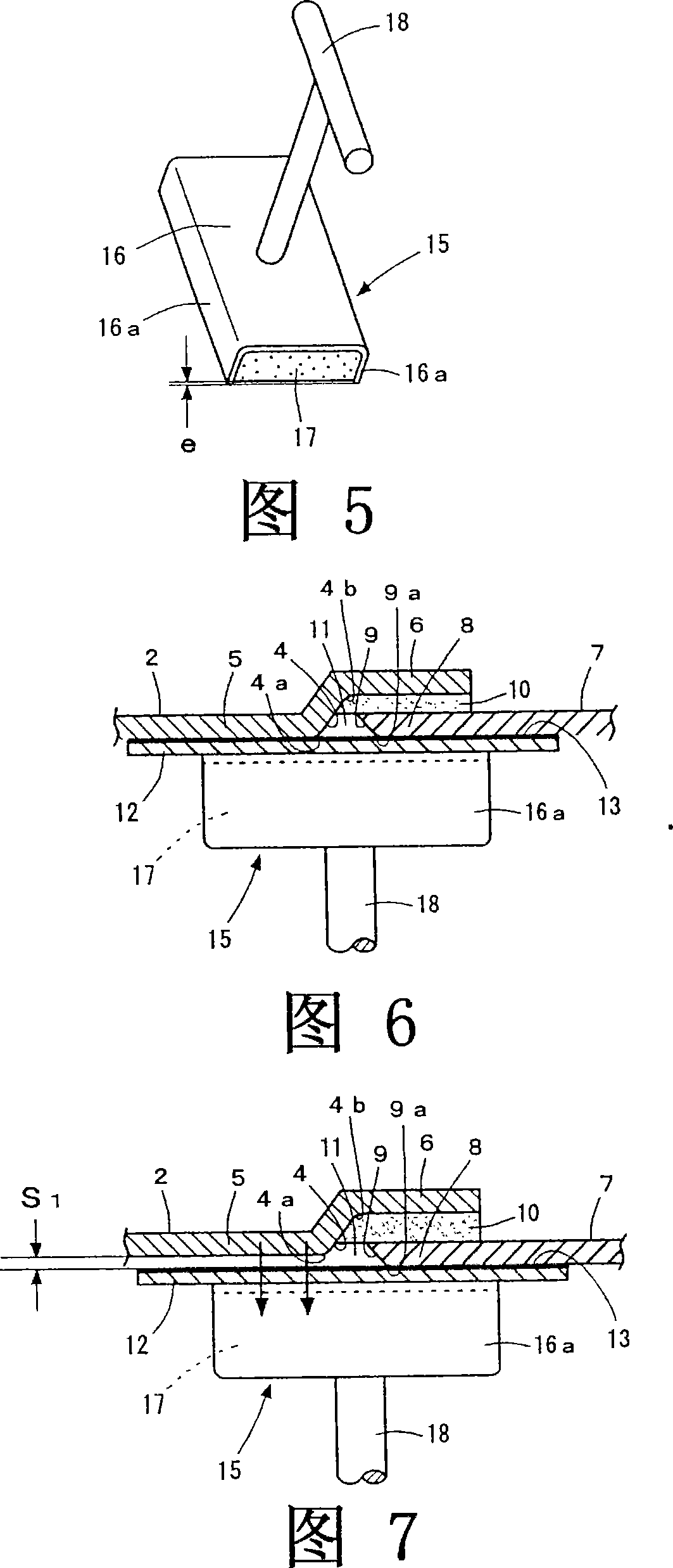
[0139] The opening surface 4 is curved to form a stepped portion at the added portion of the plate thickness of the repaired side plate body 5 and the coating thickness of the adhesive described later, and the edge side of the flat cutout portion is bent so as to be aligned with the repaired side plate body. 5 are substantially parallel to each other, thereby forming a joint piece, that is, a joint material 6 integral with the repaired side plate body 5 ....


PUM


Abstract

The present invention provides a method for joining metal plates, etc., and a grinding machine, which are suitable for repairing damaged parts of metal plates such as car bodies, and damaged parts of non-ferrous metal or non-metal peripheral walls of buildings and machinery, etc., especially Join the joint or repair part of the plate with complex curved surface to form a plane or three-dimensional consistent plane, and make it achieve a precise and beautiful effect. At the same time, it also makes this joint operation reasonable and easy to implement. The joint ends of the two repaired side plate bodies 5 and 7 that are joined to each other are arranged separately in the plate thickness direction or in the direction perpendicular to the plate thickness, and the joint pieces 6 and 31 that are integral or separate from the above-mentioned metal plates are arranged on the above-mentioned One side of the joint end, and the above-mentioned joint end and the joint pieces 6, 31 are bonded; it is characterized in that, before the above-mentioned adhesive 10 hardens, the pressing plate 12 is arranged on the surface of the other side of the above-mentioned joint end, and A suction tool 15 with a magnetic force is arranged on the surface of the pressure plate 12. By the magnetic force of the suction tool 15, the above-mentioned pressure plate 12 is closely attached to the other side surface of the above-mentioned joint end, and the above-mentioned joint end is attracted by the above-mentioned magnetic force to make it Displacement, and make the above-mentioned two joint end side surfaces form a consistent plane with the above-mentioned pressure plate 12 as a reference.

Description

technical field [0001] The present invention relates to a method for joining metal plates, etc., and a grinder, which are suitable for repairing damaged parts of metal plates such as car bodies, and damaged parts of non-ferrous metal or non-metal peripheral walls of buildings and machinery, etc. In particular, it is possible to form a flat or three-dimensional consistent plane by joining the joint or repaired part of the plate body with complex curved surfaces, and achieve a precise and beautiful effect. At the same time, it also makes this joint operation reasonable and easy to implement. Background technique [0002] For example, when joining metal plates, generally, methods of overlapping or butting the metal plates, welding the joint plate against the joined metal plates, and fixing with rivets or screws are generally used. [0003] However, there will be the following problems: the thermal deformation of the metal plate during welding will cause residual stress; the imp...

Claims


Application Information

Patent Timeline
Patent Type & Authority Applications(China)
IPC IPC(8): F16B11/00F16B5/02B24B23/04F16B5/08
CPCF16B11/006B24B23/04
Inventor 本桥孝雄
Owner 川真田博康
Why Eureka
Try Eureka