Driving method of display apparatus in which a handwriting can be overwritten on the displayed image

a technology of display apparatus and driving method, which is applied in the direction of static indicating devices, instruments, optics, etc., can solve the problems of increasing power consumption, difficult to ensure reliability, and difficult to commercialize liquid crystal devices, so as to avoid a lowering of display quality

Inactive Publication Date: 2006-08-24
CANON KK
View PDF18 Cites 59 Cited by
  • Summary
  • Abstract
  • Description
  • Claims
  • Application Information

AI Technical Summary

Benefits of technology

[0024] Further, in the case of effecting a drive for erasing an additional image while leaving only a gradation image, no flickering or the like is not caused to occur. As a result, it is possible to avoid a lowering in display quality.

Problems solved by technology

A liquid crystal display device is known as the display device but has been accompanied with problems when it is provided with a pen input function.
More specifically, most of liquid crystals have no memory characteristic, so that it is necessary to continuously apply a voltage during display (input of graphic or characters), thus resulting in an increase in power consumption.
On the other hand, with respect to liquid crystals having a memory characteristic, it is difficult to ensure reliability on the assumption that the resultant liquid crystal device is used in various environments as in the wearable PC.
As a result, it is difficult to commercialize the liquid crystal device.
If the frequency of rewriting operation is low, the trail of the pen is displayed late on the picture area even when the pen is moved on the picture area, so that a user feels a considerable inconformity.
As a result, a display quality is lowered.
In some cases, such an “undo” function that only an additional image written with a pen or the like is erased so that the display state is returned to a previous state before writing of the additional image is added to the display apparatus, but when a reset drive is performed in such cases, flickering is caused to occur, thus lowering a display quality.

Method used


Image

  • Driving method of display apparatus in which a handwriting can be overwritten on the displayed image
  • Driving method of display apparatus in which a handwriting can be overwritten on the displayed image
  • Driving method of display apparatus in which a handwriting can be overwritten on the displayed image

Examples


first embodiment

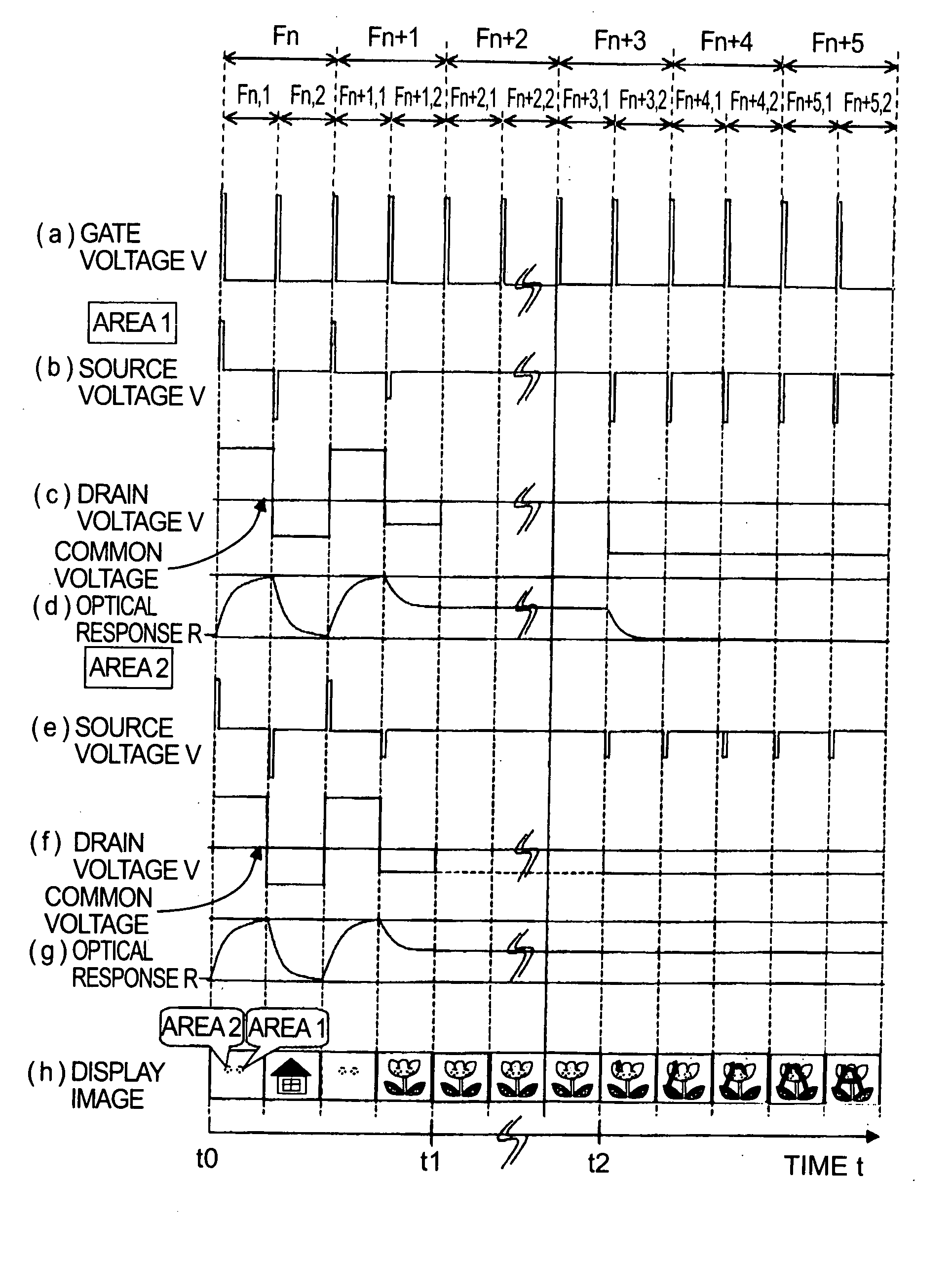
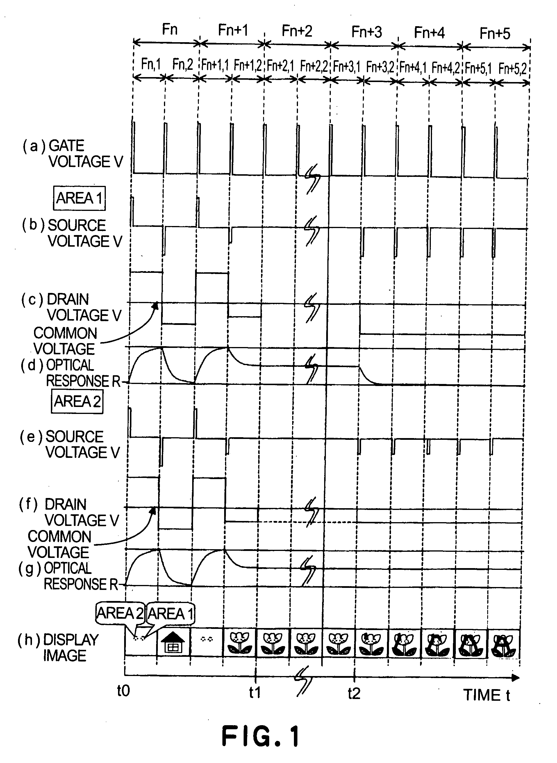
[0052]FIG. 1 is a drive waveform used in this embodiment according to the driving method of electrophoretic display apparatus of the present invention.

[0053]FIG. 1 shows a gate voltage at each pixel (a voltage applied to a gate electrode disposed at each pixel) at (a), a source voltage in an “area 1” shown at (h) (a voltage applied to a source electrode disposed at a pixel corresponding to the “area 1”) at (b), a corresponding drain voltage (a voltage applied to the pixel electrode 13a) at (c), an optical response in the “area 1” at (d), corresponding voltages or optical response in an “area 2”, shown at (h), at (e) to (d), and a display image at (h).

[0054] The display apparatus of the present invention effects display by using a driving method including separated three steps different in driving (operation) manners.

(1) First Drawing Step

[0055] In this step, image display is performed by a signal from the first image creation means 2. This drawing step is performed in a period ...

second embodiment

[0086] In this embodiment, the display apparatus is driven in the same manner as in First Embodiment except that the second drawing step (3) is performed by rewriting only a pen input area (pixel) to black and a voltage is not applied to other pixels.

[0087]FIG. 9 shows a drive waveform in this embodiment.

[0088] FIGS. 9(a) to (h) correspond to FIGS. 1(a) to (h), respectively, illustrating respective voltage pulses and optical response, wherein identical signs represent identical meanings.

[0089] Similarly as in First Embodiment, in the first drawing step (t0 to t1), the reset drive and the writing drive are performed at all the pixels. In the second drawing step (t2 or later), however, only image data such as pen input line or character data are sent to the display panel, and data of a previous (original) image as a background image are not read from the graphic memory. Accordingly, the previous image data are not subjected to image composition with the pen input image in the graph...

third embodiment

[0104] In this embodiment, the electrophoretic display apparatus shown in FIGS. 3 and 4 is driven in the principally same manner as in First Embodiment through the first drawing step, the memory display step, and the second drawing step and the drive waveforms which are identical to those in First Embodiment.

[0105] The first drawing step is performed by the reset drive and the writing drive. At the time t1, the first drawing step is terminated and after the data line drive voltage becomes 0 V, the immediately previous display image is memory-displayed.

[0106] When external writing with, e.g., a dedicated pen is performed on the display picture area, the second drawing step is performed.

[0107] In this embodiment, in the case where the pen input is effected, information from the digitizer 31 is compared and combined with the image information finally stored in the memory of the first image creation means, in the same manner as in First Embodiment.

[0108] The composite image data is ...


PUM


Abstract

A display device is driven by a driving method including a first drawing step of displaying an image by controlling a display medium on the basis of a signal from first image creation means, and a second drawing step of overwriting a handwritten image on the displayed image by controlling the display medium on the basis of a signal from second image creation means. In the first drawing step, an image is rewritten by a reset drive for resetting a display state and a writing drive for writing an image, and in the second drawing step, the writing drive is performed without effecting the reset drive.

Description

TECHNICAL FIELD [0001] The present invention relates to a driving method of a display device capable of displaying an image by controlling distribution of electrophoretic particles (charged particles) and capable of effecting writing of an additional handwritten image such as a line image or a character image to an image, such as a gradation image. BACKGROUND ART [0002] With development of information equipment, the needs for low-power and thin display apparatuses have grown, so that extensive study and development have been made on display apparatus fitted to these needs. Such display apparatuses includes a display device which permits handwriting input of graphic and character images while effecting pressing with a pen (stylus) or finger without using a keyboard (hereinafter, this function is referred to as a “pen input function”) in view of use in outdoors, power saving and spacing saving. This display device is used in a wearable PC (personal computer), an electronic note pad, e...

Claims


Application Information

Patent Timeline
Patent Type & Authority Applications(United States)
IPC IPC(8): G09G3/34G09G5/08G09G5/36
CPCG09G3/344G09G5/08G09G5/363G09G2300/08G09G2310/04G09G2310/061G09G2320/0247G09G2320/0276
Inventor YOSHINAGA, HIDEKIMORI, HIDEOGODEN, TATSUHITOSHIKINA, NORIYUKI
Owner CANON KK
Why Eureka
Try Eureka