
Starter motor solenoid with variable reluctance plunger

A solenoid and starter technology, which is used in the starting of the engine, the electromagnet with the armature, the starting of the motor for the engine, etc.

Active Publication Date: 2013-05-29
REMY TECHNOLOGIES LLC
View PDF6 Cites 2 Cited by
  • Summary
  • Abstract
  • Description
  • Claims
  • Application Information

AI Technical Summary

Problems solved by technology

However, the holding coil remains energized for a much longer period of time than the pull-in coil before the vehicle starts

Method used


Image

  • Starter motor solenoid with variable reluctance plunger
  • Starter motor solenoid with variable reluctance plunger
  • Starter motor solenoid with variable reluctance plunger

Examples


Embodiment Construction

[0042] overall starter structure

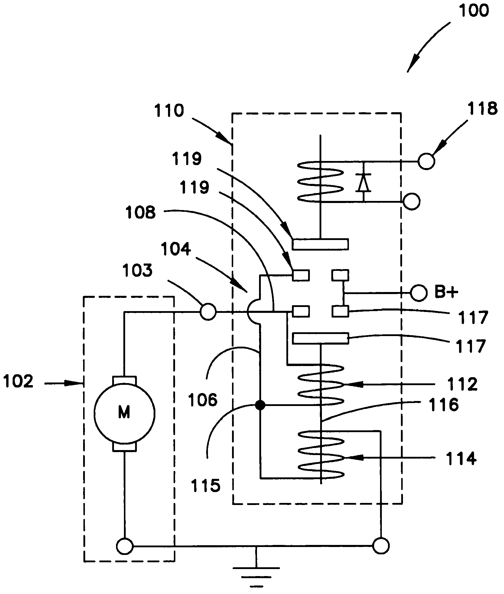
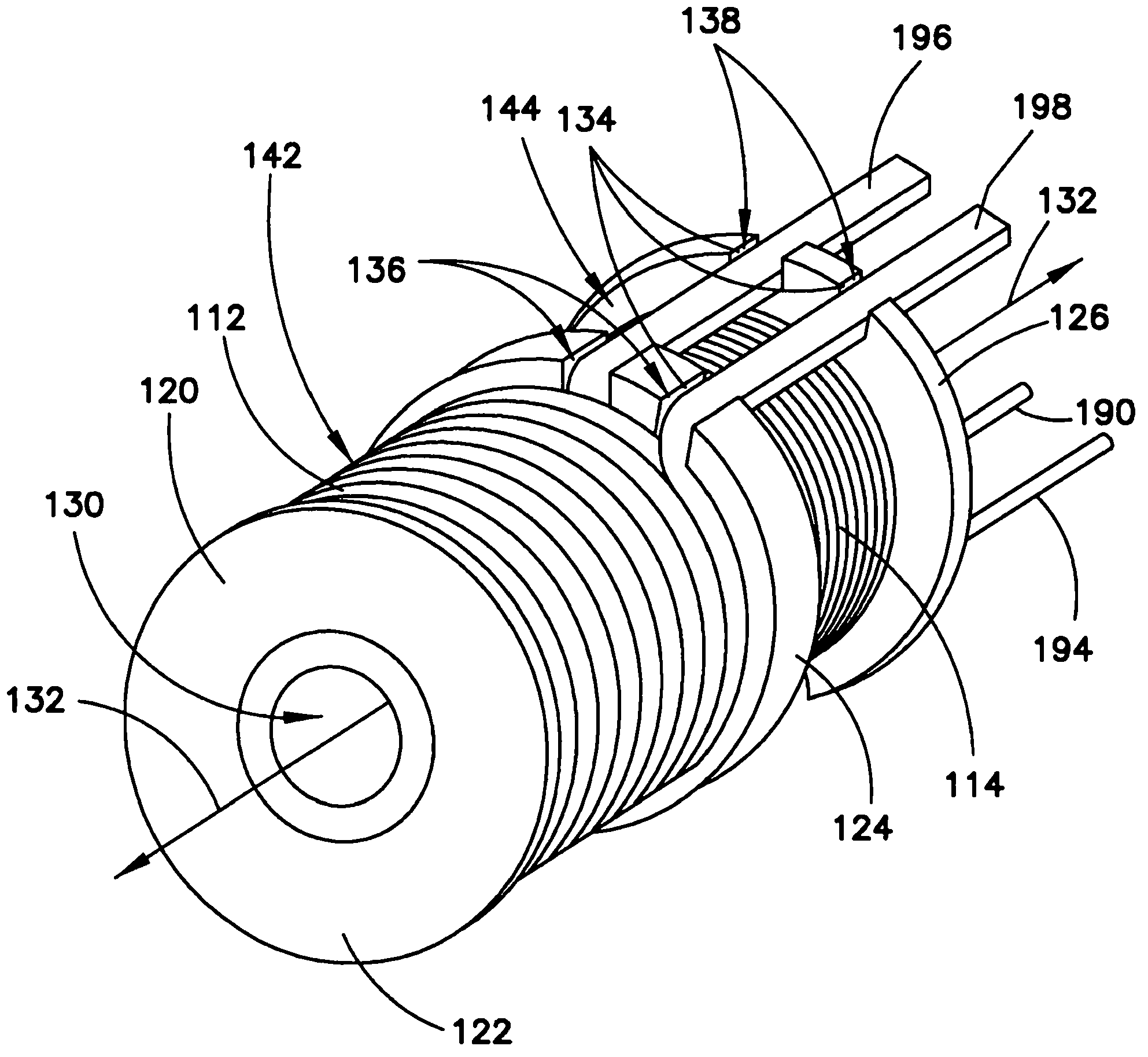
[0043] refer to figure 1 , in at least one embodiment, a starter 100 for a vehicle includes a motor 102 and a solenoid 110 . although figure 1 Not shown in , but starter 100 also includes a drive mechanism and pinion, similar to that referenced above Figure 15 A conventional starter assembly 200 is depicted. figure 1 The electric motor 102 in the embodiment of the present invention is disposed in a motor circuit 104 configured to connect the electric motor to a vehicle battery (not shown) via the B+ terminal. A solenoid 110 is provided in the motor circuit 104 to facilitate connecting the motor to the vehicle battery. The solenoid includes a pull-in coil 112 , a hold coil 114 , a plunger 116 and an ignition switch 118 .

[0044] figure 1 The motor circuit 104 includes a first current path 106 and a second current path 108 configured to provide electrical power to the electric motor 102 . The first current path 106 starts at the B+ ...


PUM


Abstract

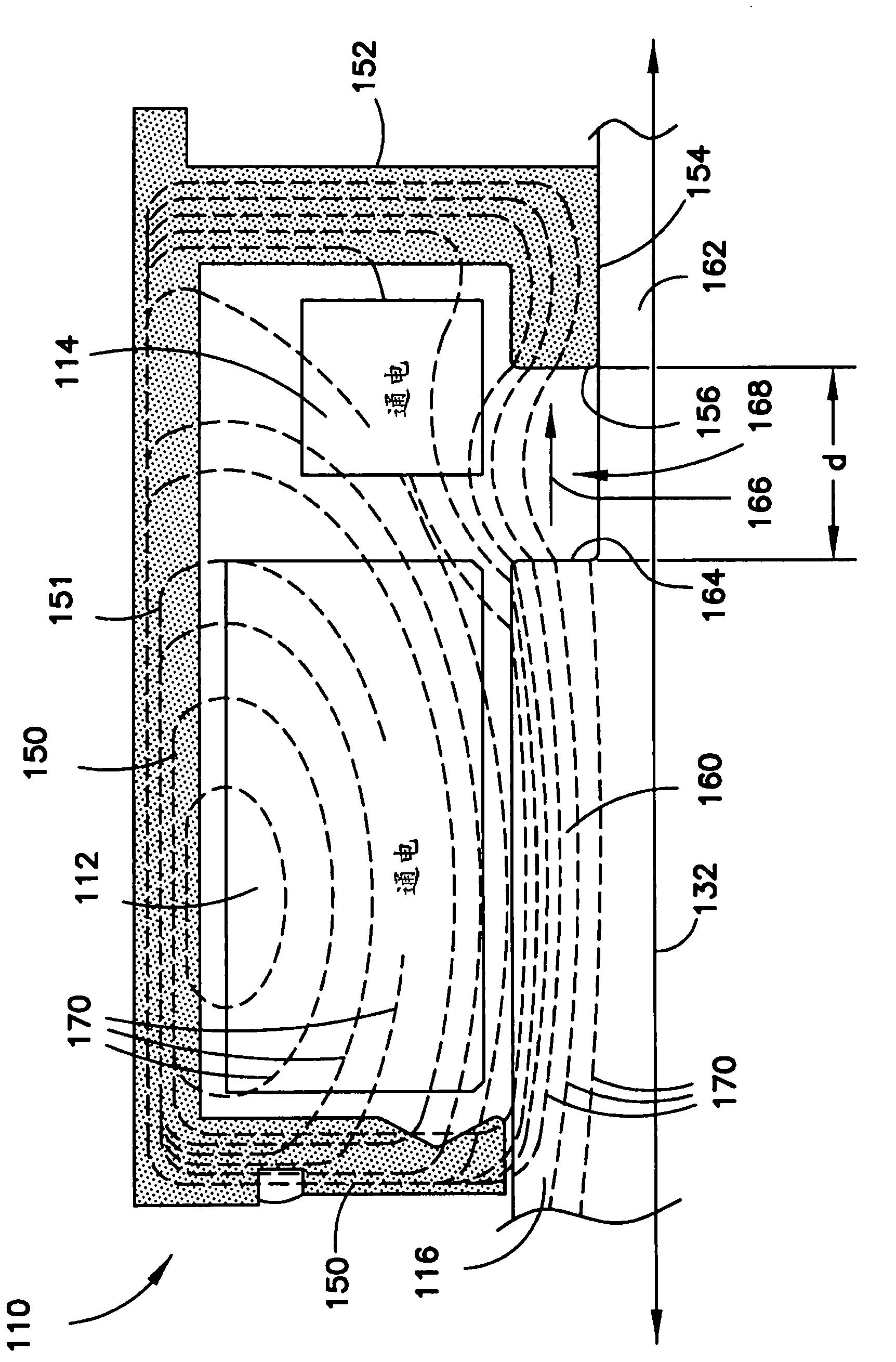
A solenoid for a vehicle starter includes at least one coil with a passage extending through the coil. A plunger is slideably positioned within the passage and configured to move in an axial direction between a first position and a second position. The plunger includes a substantially cylindrical outer surface portion with a circumferential notch formed in the outer surface portion. The at least one coil may include a pull-in coil and a hold-in coil wound on a spool. A plate member is positioned at one end of the spool and is separated from the plunger by a radial distance. The radial distance varies when the plunger moves in the axial direction as a result of the notch moving in relation to the plate member. A sleeve member may be coupled to the plunger such that the sleeve member covers the circumferential notch formed in the plunger.

Description

technical field [0001] This application relates to the field of vehicle starters, and more particularly, to solenoids for starter motor assemblies. Background technique [0002] Starter motor assemblies that assist in starting an engine, such as a vehicle engine, are well known. Figure 15 A conventional starter motor assembly is shown in . The starter motor assembly 200 of FIG. 23 includes a solenoid 210 , a motor 202 , and a drive mechanism 204 . The solenoid 210 includes a coil 212 that is energized by the battery when the ignition switch is closed. When solenoid 212 is energized, plunger 216 moves in a linear direction causing shift lever 205 to pivot and force pinion 206 to mesh with the ring gear of the vehicle's engine (not shown). When the plunger 216 reaches the plunger stop, the electrical contacts close, thereby connecting the motor 202 to the battery. The energized electric motor 202 then rotates and provides output torque to the drive mechanism 204 . The dri...

Claims


Application Information

Patent Timeline
IPC IPC(8): H02K41/00
CPCF02N19/00H02K41/03H01F7/081H01F2007/1692H01F7/1607H01F7/1833F02N2011/0892H01F7/13H01F7/1827F02N11/0851F02N11/087F02N11/0862H01F2007/086
Inventor S·P·桑迪琴M·D·布拉德菲尔德
Owner REMY TECHNOLOGIES LLC
Learn More