Rail transit double-contact-rail power supply system

A technology for rail transit and power supply systems, applied in power rails and other directions, can solve problems such as long-term corrosion effects of stray currents that cannot be fundamentally eliminated, affecting the safety and service life of structures and metal facilities, and threatening personal safety. Cost effective equipment investment and long-term maintenance costs, eliminate long-term corrosion effects, and avoid short-circuit failures

Inactive Publication Date: 2013-06-05
SOUTHWEST JIAOTONG UNIV
View PDF5 Cites 19 Cited by
  • Summary
  • Abstract
  • Description
  • Claims
  • Application Information

AI Technical Summary

Problems solved by technology

In particular, urban rail transit adopts DC traction, and the stray current generated by it will cause electrochemical corrosion to the steel structure of the ballast bed, the steel structure in the tunnel, and the metal pipelines along the line, thus affecting the safety and service life of these structures and metal facilities.
In addition, due to the use of running rail backflow, the potential difference generated by it to the ground may form a step voltage, threatening personal safety
[0003] The current corrosion protection measures for stray current mainly include drainage protection method, running rail resistance reduction method, stray current collection method and pipeline external coating method, etc., all of which require a lot of capital investment, and cannot fundamentally eliminate stray current and its long-term corrosion effects

Method used


Image

  • Rail transit double-contact-rail power supply system
  • Rail transit double-contact-rail power supply system
  • Rail transit double-contact-rail power supply system

Examples


Embodiment

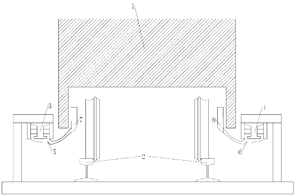
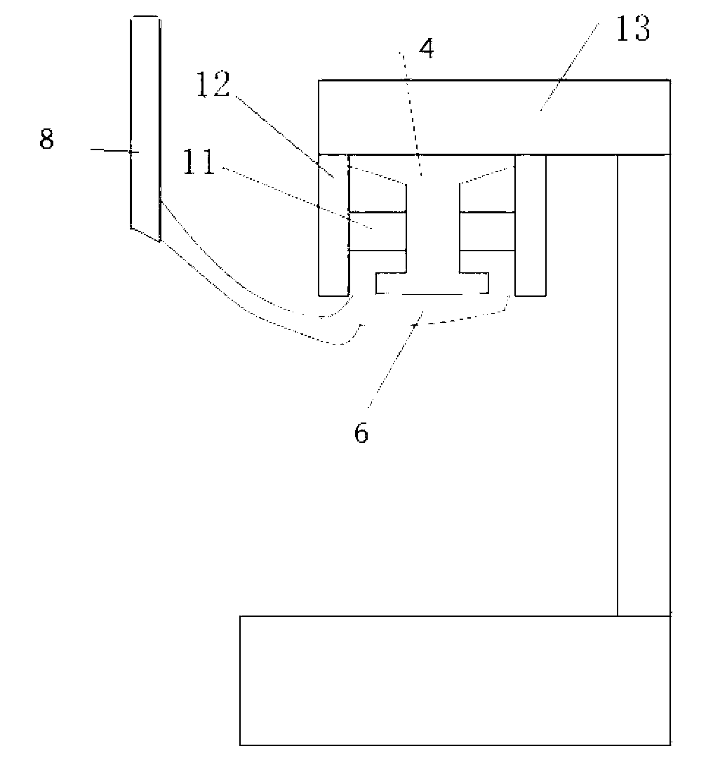
[0019] figure 1 Shown is the front view of the rail transit double contact rail power supply system. The left contact rail (power supply rail) 3 and the right contact rail (return rail) 4 are respectively arranged on the left and right sides of the running rail 2 of the rolling stock 1; the locomotive The left power receiving shoe 5 and the right power receiving shoe 6 are respectively installed on both sides of the designated part of the vehicle, and the left power receiving shoe 5 and the right power receiving shoe 6 are connected to the left contact rail (power supply rail) Contact movement on the side contact rail (return rail) 4; the left contact rail (power supply rail) 3 and the right contact rail (return rail) 4 are insulated from each other and ground, and the left power receiving shoe 5 and the right power receiving shoe 6 are connected to the bogie of the rolling stock 1 through the left insulating support 7 and the right insulating support 8 respectively. The left...


PUM


Abstract

The invention discloses a rail transit double-contact-rail power supply system. Contact rails are arranged on the left side and the right side of running rails of a rail vehicle, a power supply rail is arranged on one side while a return rail is arranged on the other side. During train operation, collector shoes on two sides of the rail vehicle are in contact movement with the contact rails mounted on the same sides and are connected with the rail vehicle through insulating supports. The left contact rail (power supply rail), the left collector shoe, a rail vehicle main circuit, the right collector shoe and the right contact rail (return rail) form a traction power supply loop. The collector shoes can be replaced by collector wheels to reduce wear and prolong service life of equipment. The double-contact-rail power supply system is an independent loop which is insulated from the running rails and the earth and supplies power to the rail vehicle main circuit, so that stray current and influences of long-term corrosion thereof are eliminated fundamentally. The double-contact-rail power supply system is convenient to mount, does not affect urban appearance and can be used for modification of existing rail transit lines as well as new construction of rail transit lines.

Description

technical field [0001] The invention relates to a rail transit double contact rail power supply system. Background technique [0002] Both electrified railways and urban rail transit traction power supply systems use running rails as the traction return system. Since the running rails are not completely insulated from the ground, the traction return current will leak to the ground and other objects through the running rails, resulting in stray currents, commonly known as stray. In particular, urban rail transit adopts DC traction, and the stray current generated by it will cause electrochemical corrosion to the steel structure of the ballast bed, the steel structure in the tunnel, and the metal pipelines along the line, thus affecting the safety and service life of these structures and metal facilities. . In addition, due to the return flow of the running rail, the potential difference generated by it to the ground may form a step voltage, threatening personal safety. [...

Claims


Application Information

Patent Timeline
IPC IPC(8): B60M1/30
Inventor 李群湛于松伟吴积钦刘炜关金发李亚楠杨兴山李子晗周菁余俊祥
Owner SOUTHWEST JIAOTONG UNIV
Why Eureka
Try Eureka