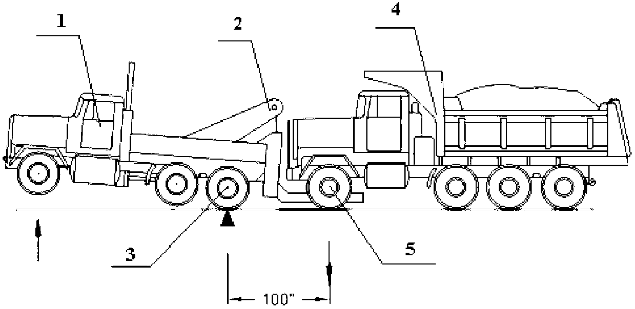
Lifting and pulling rescue vehicle
A rescue vehicle and towing technology, applied in the field of vehicle machinery, can solve problems such as inability to rescue vehicles to be rescued, failure and damage, etc., and achieve the effects of a wide range of applications, simple and flexible operation, and novel and reasonable design.
- Summary
- Abstract
- Description
- Claims
- Application Information
AI Technical Summary
Problems solved by technology
Method used
Image
Examples
Embodiment 1
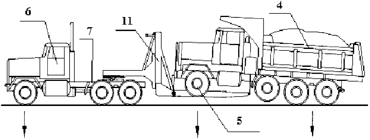
[0036] Such as figure 2 As shown, the towing rescue vehicle of the present invention includes a tractor 6 with a chassis, a vehicle frame, a power system, an electrical system and an air circuit system, the vehicle frame is arranged on the chassis, and the vehicle frame is provided with Saddle 7, wherein, a sub-frame 8 is also arranged on the chassis, and a folding arm crane 9, a pulling device 10 and a supporting device 11 are sequentially arranged on the chassis from front to back; The folding arm crane 9 is connected with the subframe 8; the folding arm crane 9 is respectively connected with the power system and the electrical system; the pulling device 10 is connected with the power system; the The supporting device 11 is arranged on the saddle 7; the supporting device 11 is respectively connected with the power system, electrical system and gas circuit system.
[0037] In the above-mentioned embodiment:
[0038] The power system is preferably a hydraulic system, and th...
Embodiment 2
[0045] Such as figure 2 , Figure 4 and Figure 5 As shown, the structural setting and distribution of a towed rescue vehicle are the same as in Embodiment 1, specifically, the following settings are also included:
[0046] The supporting device 11 includes a first supporting device 1101, a second supporting device 1102, and a lifting device 1103. The first supporting device 1101 is connected to the saddle 7, and the first supporting device 1101 is controlled by an orientation control device 1104 Connected with the second supporting device 1102, the lifting device 1103 is connected with the second supporting device 1102 through the lifting adjustment device 1105;
[0047] There are two groups of lifting devices 1103, and two groups of second supporting devices 1102. Each group of lifting devices 1103 is correspondingly connected to one group of second supporting devices 1102, and two groups of second supporting devices 1102 are connected to each other. Symmetrically arrang...
Embodiment 3
[0051] Such as figure 2 , Figure 4 , Figure 5 and Image 6 As shown, the structural setting and distribution of a towed rescue vehicle are the same as in Embodiment 2, specifically, the following settings are also included:
[0052] The second supporting device 1102 includes a bracket 110201, on which a slide rail (not shown in the figure) is arranged;
[0053] The azimuth regulating device 1104 includes an azimuth regulating power rod 110401, a fixed pin shaft 110402, and a guide rail 110403, and the guide rail 110403 is connected to the slide rail on the support 110201; one end of the azimuth regulating power rod 110401 is connected to the first support The device 1101 is connected, and the other end is connected with the bracket 110201; the fixed pin 110402 and the guide rail 110403 are located at one end of the first support device 1101 adjacent to the bracket 110201; the fixed pin 110402 is located above the guide rail 110403;
[0054] The lifting device 1103 inclu...
PUM
 Abstract
Description
Claims
Application Information
 - R&D
- Intellectual Property
- Life Sciences
- Materials
- Tech Scout
- Unparalleled Data Quality
- Higher Quality Content
- 60% Fewer Hallucinations
Browse by: Latest US Patents, China's latest patents, Technical Efficacy Thesaurus, Application Domain, Technology Topic, Popular Technical Reports.
© 2025 PatSnap. All rights reserved.Legal|Privacy policy|Modern Slavery Act Transparency Statement|Sitemap|About US| Contact US: help@patsnap.com


