Selecting method of stress suspender used for hydraulic lifting and leveling of circular structure

A technology of hydraulic lifting and lifting force, applied in the direction of lifting devices, etc., can solve problems such as hidden dangers of construction and installation, breakage of booms, overload of booms, etc.

Active Publication Date: 2015-04-08
CHINA MCC5 GROUP CORP
View PDF6 Cites 0 Cited by
  • Summary
  • Abstract
  • Description
  • Claims
  • Application Information

AI Technical Summary

Problems solved by technology

[0005] The purpose of the present invention is to provide a method for selecting a stressed suspender used for hydraulic lifting and leveling of a circular structure, which solves the problem of the failure of the suspender (or hinge) during the hydraulic lifting and leveling process of a circular structure in the past. Line) load is taken into consideration, but only some simple estimates are made, which is likely to cause severe overloading of the suspender (or hinge), resulting in breakage of the suspender (or hinge), which brings serious safety hazards to construction and installation.

Method used


Image

  • Selecting method of stress suspender used for hydraulic lifting and leveling of circular structure
  • Selecting method of stress suspender used for hydraulic lifting and leveling of circular structure
  • Selecting method of stress suspender used for hydraulic lifting and leveling of circular structure

Examples


Embodiment 1

[0043] A method for selecting a stressed suspender used for hydraulic lifting and leveling of a circular structure, comprising the following steps:

[0044] (a) Assuming that the total number of suspenders installed on the disc or ring structure is Z, the area where the Z suspenders are located is divided into a working area and a non-working area. The number of suspenders in the working area is Zg, and the non-working area The number of booms inside is Zf, and Zf=Z-Zg, where Z, Zg, and Zf are all positive integers;

[0045] (b) Assume that m sets of jacks are placed in series on each boom, the lifting force of a single jack is Pg, and the force of each working boom is Ng, then, Ng=m×Pg;

[0046] (c) Find the distance rc from the total resultant force Nc to the centerline of the disc or ring structure;

[0047] (d) Find the functional relationship between the lifting force Pg of a single jack and the number of jacks m, the number of booms Zg in the work area, the total number...

Embodiment 2

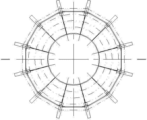
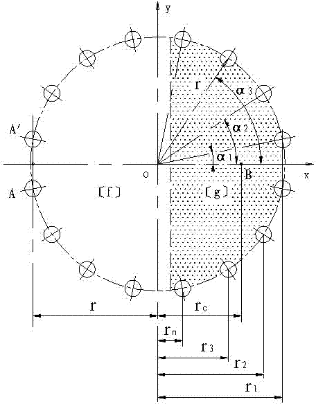
[0052] Such as image 3 , Figure 4 As shown, in this embodiment, on the basis of Embodiment 1, the number of suspenders is firstly optimized so that the total number of suspenders Z is an even number equal to or greater than 8, and then the position of the suspenders is optimized so that the suspenders It is distributed in a circular shape on a circular structure, and the distance between two adjacent suspenders is equal, which is convenient for direction adjustment and standardization, and at the same time, the force is more reasonable.

[0053] Next, refine the entire selection method:

[0054] First, calculate the position of the resultant force.

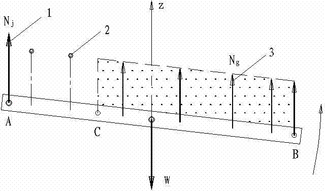
[0055] According to the principle of moment balance, the sum of the product of the stress Ng of each working boom and the corresponding stress arm Li is equal to the product of the self-weight W of the disc or ring structure and the corresponding stress arm r, that is (1-1);

[0056] ...


PUM


Abstract

The invention discloses a selecting method of a stress suspender used for hydraulic lifting and leveling of a circular structure. The selecting method comprises the following steps of (a) assuming that the total number of suspenders is Z, the number of suspenders in a work area is Zg, the number of suspenders in a non-work area is Zf, and Zf = Z-Zg; (b), assuming that m jacks are arranged on each suspender in series, lifting force of each jack is Pg, and stress of each work suspender is Ng, and Ng = m*Pg; (c), determining the distance between the total resultant force Nc and a center line of the circular structure; (d), determining a function relation between the PG, the m, the Zg, the Z and the self weight W of the circular structure; (e), determining work stress Nj of a static load suspender; and (f), selecting a proper suspender specification. By the adoption of the method, the stress of a lifting and leveling suspender of the circular structure can be calculated accurately, thus a basis can be provided for selection of a proper suspender, and safe proceeding of construction can be ensured.

Description

technical field [0001] The invention relates to the field of engineering construction, in particular to a method for selecting a stressed suspender used for hydraulic lifting and leveling of a circular structure. Background technique [0002] In engineering construction and installation, there are many circular (disc or ring) structures, such as water tanks, which are large steel grid structures or reinforced concrete structures, and most of them require overall hydraulic lifting and leveling. The lifting boom can be According to the lifting force, select steel strands or round steel bars with appropriate specifications or diameters, and use steel strands or round steel jacks for lifting. There are certain differences in structure between steel strands and round steel jacks, but the working principle exactly the same. [0003] The principle of circular (disc or ring) leveling and rotating is to change the symmetrical force during translation, break the original moment balan...

Claims


Application Information

Patent Timeline
Patent Type & Authority Patents(China)
IPC IPC(8): B66F3/36
Inventor 乔秀坤
Owner CHINA MCC5 GROUP CORP
Why Eureka
Try Eureka