Radial locking type over-load protection shaft

An overload protection and shaft wall technology, which is applied in the field of shaft transmission, can solve problems such as poor reliability of the anti-overload structure, overload fracture of the transmission shaft, damage of transmission parts, etc., and achieve the effect of improving smoothness of shifting, reducing loss and long service life

Inactive Publication Date: 2014-11-05
NANPING AUTO FORGING & STAMPING FACTORY
View PDF8 Cites 0 Cited by
  • Summary
  • Abstract
  • Description
  • Claims
  • Application Information

AI Technical Summary

Problems solved by technology

[0005] The present invention aims to overcome the shortcomings that the transmission shaft of a motor vehicle is prone to breakage when it is overloaded, or causes damage to related transmission components, and the reliability of the anti-overload structure in the prior art is poor, and provides a power transmission that can be cut off when overloaded. So as to prevent the transmission shaft from breaking, and at the same time, the radial locking overload protection shaft with better reliability

Method used


Image

  • Radial locking type over-load protection shaft
  • Radial locking type over-load protection shaft
  • Radial locking type over-load protection shaft

Examples


Embodiment 1

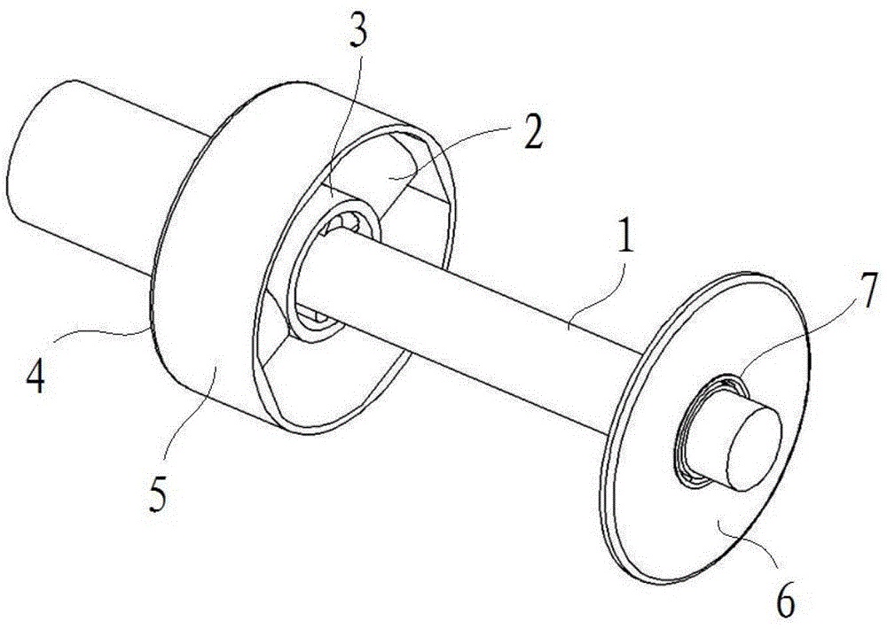
[0025] like figure 1 In the shown embodiment 1, a radial locking overload protection shaft includes a transmission shaft and a support body. The transmission shaft is composed of a first shaft 1 and a second shaft 3, wherein the second shaft is a hollow structure, and the first The shaft is located inside the second shaft, and the two shafts are concentric. A pair of hydraulic cylinders 2 are arranged on the second shaft, and the two hydraulic cylinders are symmetrically arranged on the second shaft. The support body includes a left mounting base 4, a right mounting base 6 and a connecting frame body 5, the left mounting base and the right mounting base are connected through the connecting frame body 5, wherein the left mounting base is fixedly connected to the second shaft, and the center of the right mounting base is provided with The through hole is connected with the first shaft through the rolling bearing 7.

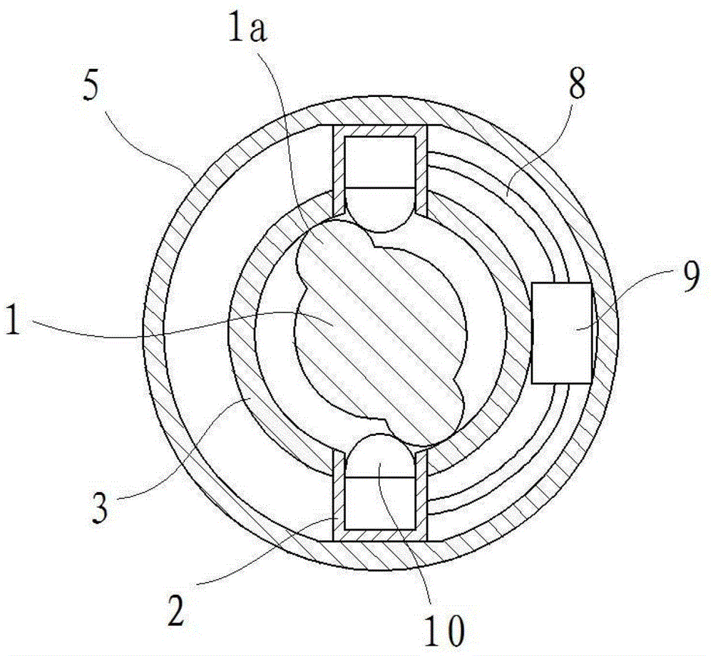
[0026] like figure 2 As shown, the hydraulic cylinder runs...

Embodiment 2

[0030] like Figure 4 In said embodiment 2, a radial locking type overload protection shaft includes a transmission shaft and a support body, the transmission shaft includes a first shaft 1 and a second shaft 3, wherein the second shaft is a hollow structure, and the first shaft Located inside the second axis, and the two axes are concentric. Two pairs of hydraulic cylinders 2 are arranged on the second shaft, the central axes of the four hydraulic cylinders are located on the same cross section of the second shaft, and the included angle between adjacent hydraulic cylinders is 90 degrees. The support body includes a left mounting seat, a right mounting seat and a connecting frame body 5, the left mounting seat and the right mounting seat are connected through the connecting frame body, wherein the left mounting seat is fixedly connected to the second shaft, and the center of the right mounting seat is provided with a through hole. It is connected with the first shaft through...


PUM


Abstract

The invention discloses a radial locking type over-load protection shaft which comprises a transmission shaft. The transmission shaft comprises a first shaft and a second hollow shaft, the first shaft is located in the second shaft and is concentric with the second shaft, at least one pair of hydraulic cylinders is arranged in the peripheral direction of the second shaft, an energy storage valve is connected between each pair of hydraulic cylinders, the hydraulic cylinders penetrate through a shaft wall of the second shaft, openings of the hydraulic cylinders face to the first shaft, ejecting blocks capable of sliding relative to cylinder bodies are arranged in the cylinder bodies of the hydraulic cylinders, and lugs butting against the ejecting blocks are arranged on the circumferential surface of the first shaft. The radial locking type over-load protection shaft can cut off power transmission during over-load so as to prevent the transmission shaft from being broken and simultaneously is good in reliability.

Description

technical field [0001] The invention belongs to the field of shaft transmission, and in particular relates to a transmission shaft structure with overload protection function, which is especially suitable for the transmission system of motor vehicles. Background technique [0002] In the field of mechanical transmission, especially in motor vehicles, the power generated by the engine needs to be transmitted to the wheels through the transmission system. For cars with front-engine front-wheel drive, the power of the engine is transmitted to the two half-shafts of the front axle through the transmission, final drive, differential, etc. to drive the wheels to rotate, while the car with front-engine rear-wheel drive That is to say, after the power passes through the transmission, it needs to be transmitted to the final drive of the rear axle through the main drive shaft. For off-road vehicles and trucks, in order to increase the climbing performance and passing performance of t...

Claims


Application Information

Patent Timeline
Patent Type & Authority Patents(China)
IPC IPC(8): F16D7/04
Inventor 陈学福
Owner NANPING AUTO FORGING & STAMPING FACTORY
Why Eureka
Try Eureka