
Gluing unit of CTP (Computer To Plate)

A technology of plate making machine and cot, applied in the direction of coating, device for coating liquid on the surface, etc., can solve the problems of low work efficiency, dirty layout, etc. The effect of printing time

Inactive Publication Date: 2013-06-12
苏州裕同印刷有限公司
View PDF10 Cites 1 Cited by
  • Summary
  • Abstract
  • Description
  • Claims
  • Application Information

AI Technical Summary

Problems solved by technology

[0003] The purpose of the present invention is to provide an improvement of the gluing unit of a CTP plate-making machine, so as to solve the problems in the prior art that the printing plate produced by the gluing unit of the CTP plate-making machine is seriously dirty and the work efficiency is low.

Method used


Image

  • Gluing unit of CTP (Computer To Plate)
  • Gluing unit of CTP (Computer To Plate)

Examples


Embodiment Construction

[0013] The invention will be described in further detail below in conjunction with the accompanying drawings and examples, but the following examples are only examples of the present invention, and do not represent the limited scope of rights of the present invention. The scope of protection of the present invention is defined in the claims prevail.

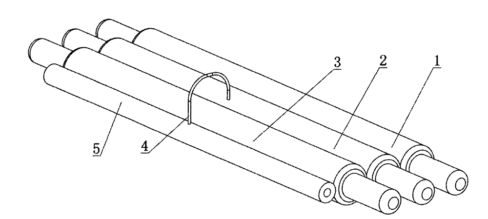
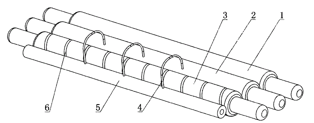
[0014] according to figure 1 and figure 2 The present invention is described in detail. A gluing unit of a CTP plate-making machine according to the present invention includes a rubber pressing roller 1 , a gluing roller 2 , a gluing roller 3 , and a gluing tube 5 installed on a frame (not shown in the figure). Three glue outlet holes (not shown in the figure) are evenly distributed on the upper glue pipe 5, and a glue outlet pipe matched with the glue outlet hole is provided on the glue outlet hole. The roll surfaces of the upper rubber roller are respectively tangent to the roller surfaces of the pressure rubber roller and ...


PUM


Abstract

The invention discloses a gluing unit of a CTP (Computer To Plate). The gluing unit comprises a dandy roller, a gluing roller, a glue homogenizing roller and a gluing tube which are mounted on a rack; at least three glue outlet holes are evenly formed on the gluing tube; and glue outlet tubes matched with the glue outlet holes are arranged on the glue outlet holes. The technical essential of the invention is as follows: the roller surface of the gluing roller is tangent to the roller surfaces of the dandy roller and the glue homogenizing roller; and a thread groove is formed outside the glue homogenizing roller. The problems of serious dirty on the plate surface of the plate printed by the gluing unit of the CTP in the prior art, low working efficiency and the like are solved. The dirt plate phenomenon is eliminated, a printer can continuously operate, an inferior-quality product and the halt in the intermediate link are avoided, and further the production cost is lowered.

Description

technical field [0001] The invention belongs to the technical field of plate-making equipment in the printing industry, in particular to a gluing unit of a CTP plate-making machine. Background technique [0002] At present, there are many publishing methods in the printing industry. The traditional method is film sunburn; now, machine-based plate making is basically used, and Agfa CTP and Founder Diaolong CTP are commonly used. The printing plate produced by the gluing unit of the traditional CTP plate-making machine is seriously dirty, and the problem of dirty layout is dealt with five minutes before printing, especially for short-run jobs. The above problems have seriously affected the printing efficiency, and a large amount of ink and plate washing solution was wasted, which increased the production cost. The main reason for the serious dirty plate is that the protective glue is not evenly coated, which causes problems when the PS plate is exposed, resulting in serious d...

Claims


Application Information

Patent Timeline
Patent Type & Authority Applications(China)
IPC IPC(8): B05C5/00B05C11/10
Inventor 唐崇钢
Owner 苏州裕同印刷有限公司
Learn More