
Dispensing machine

A medicine dispensing machine and medicine technology, applied in the field of medical devices, can solve the problems of inability to adapt, easy to miss the medicine dispensing machine, lack of control of the medicine dispensing machine, etc., and achieve the effect of high medicine dispensing accuracy

Active Publication Date: 2013-06-12
SUZHOU IRON TECH
View PDF7 Cites 1 Cited by
  • Summary
  • Abstract
  • Description
  • Claims
  • Application Information

AI Technical Summary

Problems solved by technology

[0002] In the current automated pharmacy, the transfer and transmission of medicines are realized through the medicine dispensing machine. In the existing medicine dispensing machines, elevators are often used to adjust the vertical position of the medicine dispensing machine to match the corresponding dosing tank of the medicine dispensing machine. However, the existing lift only drives the medicine dispensing machine in the vertical direction by lifting the parts, lacks the control of the movement process of the medicine dispensing machine, and needs to manually stop or start the elevator to adjust the motion state of the medicine dispensing machine, resulting in It is easy for the medicine machine to miss the position of the dosing tank, and it is necessary to fine-tune the position of the medicine dispensing machine, resulting in the slowing down of the medicine dispensing speed of the medicine dispensing machine, making the automated pharmacy unable to meet the current demand for large-scale and high-speed medicine dispensing. The medicine machine moves to the wrong dosing tank, resulting in wrong medicine dispensing by the medicine dispensing machine, which may easily cause medical accidents

Method used


Image

  • Dispensing machine
  • Dispensing machine
  • Dispensing machine

Examples


Embodiment Construction

[0023] The present invention will be described in detail below in conjunction with various embodiments shown in the accompanying drawings. However, these embodiments do not limit the present invention, and any structural, method, or functional changes made by those skilled in the art according to these embodiments are included in the protection scope of the present invention.

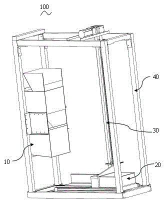
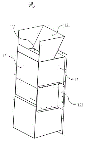
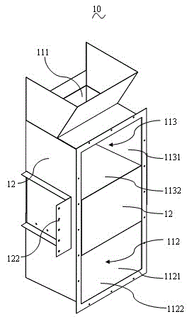
[0024] ginseng Figure 1 to Figure 7 As shown, the present invention provides a medicine dispensing machine 100, which outputs medicines through the medicine receiving assembly 10 arranged in the vertical direction, replacing the existing horizontally arranged conveyor belts, greatly reducing the cost of the medicine dispensing machine. 100 on the horizontal plane occupies the size of the space, so that more medicine dispensing machines 100 can be arranged in a limited space, and the medicine receiving assembly 10 can be supplemented with medicine through the cooperation of the transfer assembly 20 and ...


PUM


Abstract

The invention provides a dispensing machine, which comprises a transferring assembly, a lifting assembly and a control assembly, wherein the transferring assembly comprises a medicine containing cavity; the lifting assembly comprises a sliding rail extending along the vertical direction, and a sliding block positioned on the sliding rail; the transferring assembly is fixedly arranged on the sliding block and moves with the sliding block along the guide rail; the lifting assembly also comprises a first sensor positioned on a specific height on the side edge of the sliding rail; the transferring assembly comprises a main sensor corresponding to the first sensor; and the control assembly is used for stopping the sliding block when the first sensor and the main sensor are at the same height. Compared with the prior art, the dispensing machine provided by the invention is characterized in that the transferring assembly is provided with the main sensor, the first sensor, a second sensor and a third sensor are correspondingly arranged on the sliding rail, the area of the transferring assembly on the sliding rail is spaced, the stopping position of the transferring assembly is precisely controlled, and the dispensing work is efficiently finished.

Description

technical field [0001] The invention relates to the field of medical devices, in particular to a medicine dispensing machine. Background technique [0002] In the current automated pharmacy, the transfer and transmission of medicines are realized through the medicine dispensing machine. In the existing medicine dispensing machines, elevators are often used to adjust the vertical position of the medicine dispensing machine to match the corresponding dosing tank of the medicine dispensing machine. However, the existing lift only drives the medicine dispensing machine in the vertical direction by lifting the parts, lacks the control of the movement process of the medicine dispensing machine, and needs to manually stop or start the elevator to adjust the motion state of the medicine dispensing machine, resulting in It is easy for the medicine machine to miss the position of the dosing tank, and it is necessary to fine-tune the position of the medicine dispensing machine, which w...

Claims


Application Information

Patent Timeline
IPC IPC(8): B65G1/04
Inventor 罗帅平
Owner SUZHOU IRON TECH
Learn More