Method for producing a piston ring

A technology for piston rings and rings, which is applied in the field of manufacturing piston rings with interfaces, can solve problems such as unrealizable processing technology, and achieve the effects of improving grinding results, reducing wear and improving friction characteristics.

Active Publication Date: 2013-06-12
FEDERAL MOGUL BURSCHEID
View PDF6 Cites 7 Cited by
  • Summary
  • Abstract
  • Description
  • Claims
  • Application Information

AI Technical Summary

Problems solved by technology

However, this method, especially in connection with compression piston rings made of profiled wire, is not feasible from a processing-technical point of view

Method used


Image

  • Method for producing a piston ring

Examples


Embodiment Construction

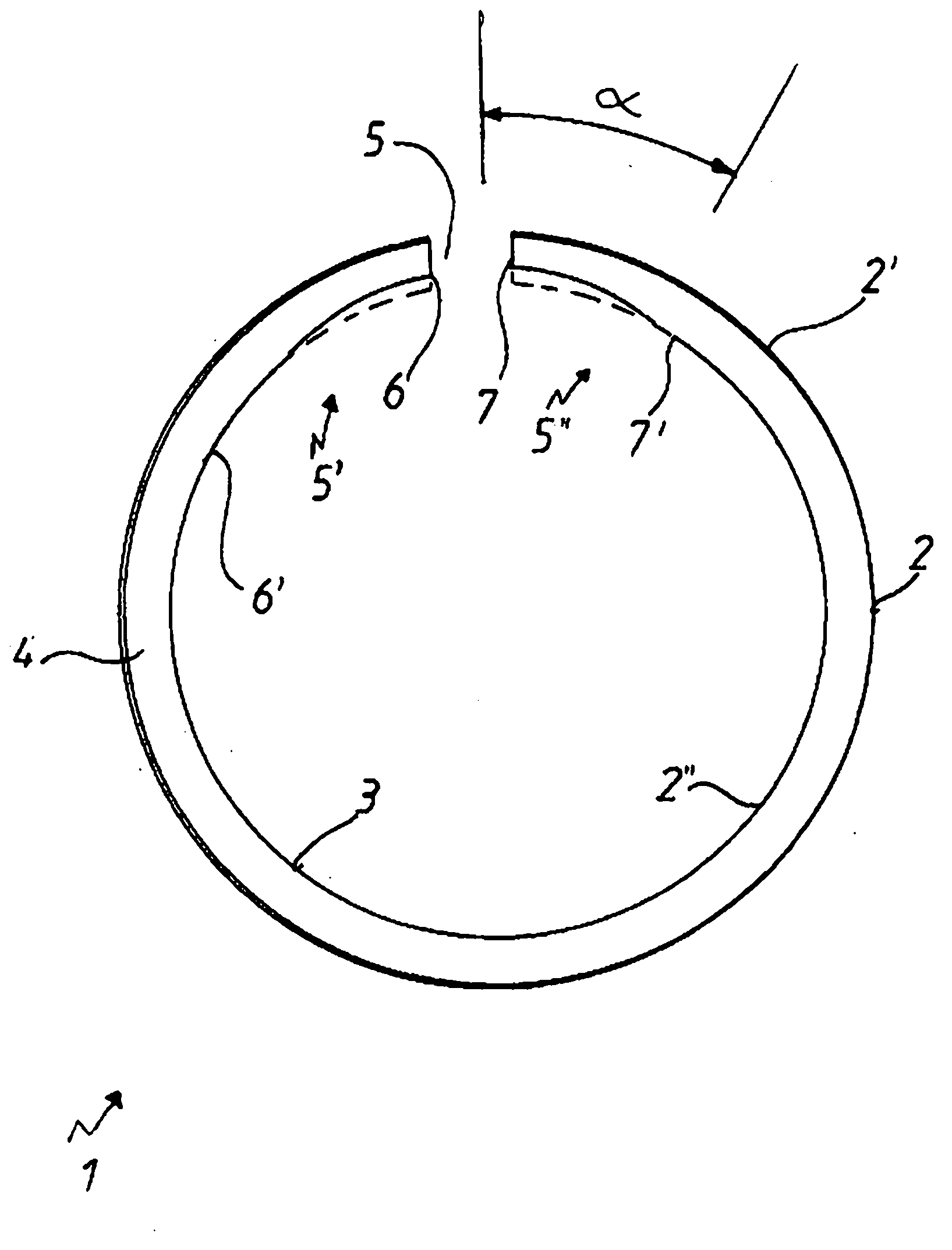
[0020] In principle, the single figure shows a piston ring 1 , in particular a compression piston ring, which in this illustration has a sliding surface 2 , an inner peripheral surface 3 and an upper ring side surface 4 . In addition, the piston ring 1 also has a connection 5 . In this exemplary illustration, the piston ring 1 is supposed to be provided with a PVD layer 2' applied in the region of the sliding surface 2. As already mentioned, such a hard sliding surface has an effect on the inherent stresses of the piston ring 1 . This is particularly the case from the point of view of the different thermal expansions between the (softer) base material and the (harder) PVD layer of the piston ring 1 , which have a negative effect especially on the interface region 5 . This means that the interface region 5 is elastically deformed radially outward and thus produces an increased contact force in this region against the friction fit, for example a cylinder liner. In order to ove...


PUM


Abstract

The invention relates to a method for producing a piston ring (1) provided with a butt joint (5), in that an annular metal main body is provided with at least one hard layer (2') at least in the area of the outer circumferential surface (2) of said main body, wherein after this coating the inner circumferential surface (3) of the piston ring is at least partially subjected to a wall-thickness-reducing material removal process.

Description

technical field [0001] The invention relates to a method for producing a piston ring provided with an interface. Background technique [0002] Due to the increasing power density, both in fast combustion engines and in diesel engines, the load on the piston rings with regard to wear and heat resistance is likewise increasing. To counteract this, piston rings are produced that are repeatedly chromed or nitrided on the sliding side, which already have a high hardness themselves. Also in the meantime, the use of piston rings with very hard layer systems, such as PVD (Physical Vapor Deposition) layers or HVOF (High Velocity Flame Injection) layers, is also conceivable with regard to the mentioned power densities. This hardness carries with it high inherent stresses which affect the annular and radial pressure distribution. [0003] These high inherent stresses produce undesired changes in the ring and changes in the radial pressure distribution both during manufacture and duri...

Claims


Application Information

Patent Timeline
Patent Type & Authority Applications(China)
IPC IPC(8): F16J9/14F16J9/26
CPCF16J9/14F16J9/26Y10T29/49281B23P15/06F02F5/00
Inventor K·迈尔
Owner FEDERAL MOGUL BURSCHEID
Why Eureka
Try Eureka