Eureka AIR delivers breakthrough ideas for toughest innovation challenges, trusted by R&D personnel around the world.

Long telescopic soot blower

A soot blower, long telescopic technology, applied in the direction of combustion product treatment, combustion method, removal of solid residue, etc., can solve the problems of non-adjustable pressure, imprecise cooperation between valve disc and valve seat, and easy leakage, etc., to achieve Avoid dead ends, reduce compression-rebound degree, and prevent leakage

Active Publication Date: 2012-01-04
江苏焱鑫科技股份有限公司
View PDF0 Cites 0 Cited by
  • Summary
  • Abstract
  • Description
  • Claims
  • Application Information

AI Technical Summary

Problems solved by technology

[0005] 3. The valve disc and valve stem in the intake valve adopt an integral design, and the valve disc, valve disc and valve seat form a rigid contact. When the valve stem is lifted upwards, the valve disc and valve seat are not matched precisely, which is easy to cause leakage
[0006] 4. The pressure of the steam outlet in the intake valve cannot be adjusted

Method used


Image

  • Long telescopic soot blower
  • Long telescopic soot blower
  • Long telescopic soot blower

Examples


Embodiment Construction

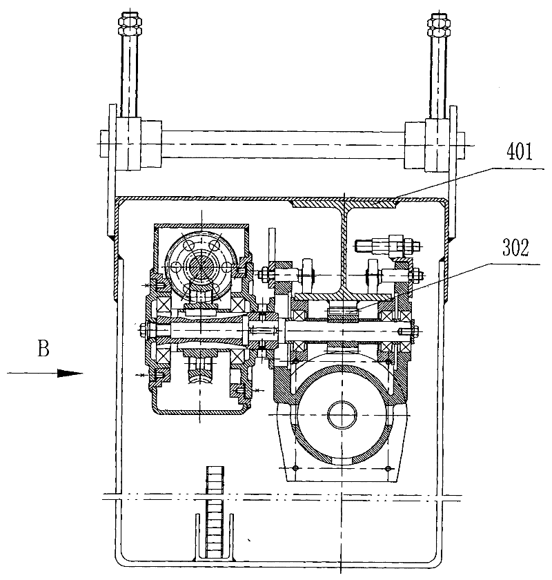
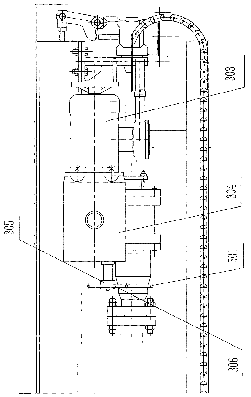
[0037] see Figure 1~3 , figure 1 It is a schematic diagram of the front structure of the long telescopic soot blower of the present invention. figure 2 for figure 1 A-A cut-away diagram. image 3 for figure 2 B direction view. Depend on figure 1 , figure 2 and image 3 It can be seen that the long telescopic sootblower of the present invention includes a box body 4, a guide rail 401 is arranged horizontally on the upper part of the box body 4, and a sports car 3 is arranged on the guide rail 401. The sports car 3 includes a motor 303 and a double output shaft reducer 304, The double output shaft reducer 304 has an input shaft and two output shafts, one output shaft is connected with the guide rail 401 through a rack and pinion pair 302, and drives the sports car 3 to reciprocate along the guide rail 401, and the other output shaft is installed There is a main drive disc 305 and a speed reducer sprocket 306, such as Figure 4 and Figure 5 , the main transmission ...


PUM


Abstract

The invention relates to a long telescopic soot blower used for removing soot and slag on the surfaces of heating furnaces in the petrochemical industry, heating furnaces in the power industry, and the like. The soot blower comprises a box body (4), a moving cart (3), an outer soot blowing pipe (5), an inner blowing pipe (12), a steam inlet valve (1) and an operation mechanism (2), wherein the moving cart (3) comprises an electromotor (303) and a double-output-shaft speed reducer (304); the other output shaft of the double-output-shaft speed reducer (304) is provided with a main driving disk (305) and a speed reducer chain wheel (306); the main driving disk (305) is provided with a semicircular annular slot (309), and a pin (308) is embedded in the slot (309) and fixedly connected with the speed reducer chain wheel (306); the outer soot blowing pipe (5) is horizontally arranged in the box body (4), and the outer edge of the outer soot blowing pipe (5) is provided with a soot blowing pipe chain wheel (501); and the soot blowing pipe chain wheel (501) is connected with the speed reducer chain wheel (306) through a chain. In the invention, the outer soot blowing pipe has no blowing dead angles; the pressure of fillers in a filler box is stable; the matching in the steam inlet valve is precise; and the pressure of a steam outlet can be regulated.

Description

(1) Technical field [0001] The invention relates to a soot blower. It is used to remove dust and slag from the surfaces of heating furnaces in the petrochemical industry, heating furnaces in the power industry, convection tube bundles on boilers, air preheaters, and economizer superheaters. It belongs to the technical field of petrochemical and electric power equipment. (2) Background technology [0002] In heating furnaces in the petrochemical industry, heating furnaces in the power industry, convection tube bundles on boilers, air preheaters, economizer superheaters, etc., sootblowers are generally used to remove dust and slag from their surfaces to reduce The exhaust gas temperature is used to improve the thermal efficiency of heating furnaces and boilers to achieve the purpose of reducing consumption and saving energy. When the smoke temperature in the furnace exceeds 550°C, a long telescopic soot blower should be used. When the sootblower is blowing soot, it makes a ...

Claims


Application Information

Patent Timeline
Patent Type & Authority Patents(China)
IPC IPC(8): F23J1/00F23J3/00
Inventor 周国华郭建文陶革新曹惠忠张春华郁金洪杨卫卢康陈世陵朱海航戴俊平陶海雄刘亚萍
Owner 江苏焱鑫科技股份有限公司
Why Eureka
Eureka Blog
Learn More