Oil seal

A technology of oil seals and sealing parts, which is applied in the direction of engine components, engine seals, mechanical equipment, etc., can solve problems such as oil leakage, and achieve the effect of improving sealing and fixing stability

Active Publication Date: 2016-01-27
NOK CORP
View PDF7 Cites 0 Cited by
  • Summary
  • Abstract
  • Description
  • Claims
  • Application Information

AI Technical Summary

Problems solved by technology

Therefore, the muddy water intruding from the dustproof lip 53 is drawn into the main lip 52, and there is a problem of oil leakage.

Method used


Image

  • Oil seal
  • Oil seal
  • Oil seal

Examples


Embodiment

[0075] Next, embodiments of the present invention will be described with reference to the drawings.

no. 1 example

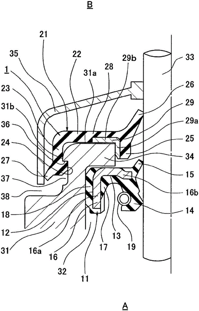
[0077] figure 1 A main part cross section of the oil seal 1 according to the first embodiment of the present invention is shown. The oil seal 1 according to this embodiment is installed on the end surface of the housing 31 through the first sealing member (also referred to as the oil seal main body) 11 installed on the inner periphery of the shaft hole 32 of the housing 31 and the opening peripheral portion of the shaft hole 32 . It is formed by combining the second sealing member (also referred to as a dust seal) 21 of the part, and is configured as follows. In addition, the shaft 33 inserted into the shaft hole 32 is a vertical shaft, specifically, a steering shaft in a power steering unit of a vehicle such as an automobile. The bottom of the figure is the inside A of the machine, and the top is the outside B of the machine. At the outer end of the casing 31, an inward (radially inward) flange portion 34 is integrally provided on the periphery of the shaft hole opening. ...

no. 2 example

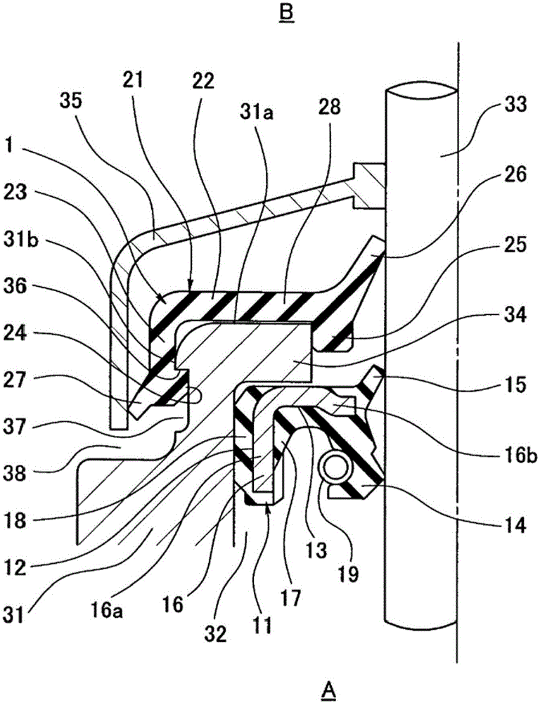
[0086] In the above-mentioned first embodiment, the second sealing member 21 is formed by the integral molding of the rubber-like elastic body 28, and at the same time, the metal ring 29 is embedded in the position from the end surface covering part 22 to the inner peripheral insertion part 25 to increase its strength. But as a second example, as in figure 2 As shown, the metal ring 29 may be omitted, and in this case, the second sealing member 21 is molded only from the integral molding of the rubber-like elastic body 28 . In this case, although the strength is slightly lowered, the manufacturing cost of the second sealing member 21 can be reduced, and since the flexibility of the member is improved, the installation work can be facilitated. Other configurations and functions and effects of this second embodiment are the same as those of the above-mentioned first embodiment. In addition, similar to the first embodiment, the lower end of the inner peripheral insertion portio...


PUM


Abstract

Provided is an oil seal configured so that the sealing ability of the oil seal is improved by preventing muddy water from accumulating on the upper part of a dust lip disposed on the side which faces the outside of the machine. To obtain such an oil seal, a second seal member is provided on the side of a first seal member which faces the outside of the machine, the first seal member having a main lip, a first dust lip, and an affixation section affixed to a housing. The second seal member integrally has: an end surface covering section for covering an end surface of the housing; an outer peripheral engagement section fitted over the outer peripheral surface of the housing from one side in the axial direction and engaged with a stepped engagement section provided on the outer peripheral surface of the housing to retain the second seal member at the housing; an inner peripheral engagement section fitted to the inner peripheral surface of the shaft hole in the housing from the one side in the axial direction; and a second dust lip in close contact with the shaft on the side of the first dust lip which faces the outside of the machine.

Description

technical field [0001] The present invention relates to an oil seal as a type of sealing device. The oil seal of the present invention is used, for example, as a shaft seal in a power steering unit of a vehicle such as an automobile, or in other general industrial machines. Background technique [0002] Conventionally, as oil seals used as shaft seals in power steering parts of vehicles such as automobiles, there are known image 3 The oil seal 51 shown in , the oil seal 51 in the installed state has: the main lip 52, which is arranged towards the inner side A of the machine, and seals the sealing fluid such as oil; foreign matter sealing (refer to Patent Document 1). [0003] However, when this oil seal 51 is mounted on an actual machine, since the axis is a vertical axis, the dustproof lip 53 is arranged with its lip front end facing upward. [0004] On the other hand, in regions with insufficient road maintenance such as foreign countries, the dust environment is harsh,...

Claims


Application Information

Patent Timeline
IPC IPC(8): F16J15/3204F16J15/3232F16J15/3252F16J15/3276
CPCF16J15/3232
Inventor 滨本耕吉
Owner NOK CORP
Why Eureka
Try Eureka