Coolant drainage system and method for electric machines

A technology of exhaust system and coolant, applied in cooling/ventilation devices, electromechanical devices, electrical components, etc., can solve the problems of large rotation loss of motor and increase of coolant, etc.

Active Publication Date: 2013-06-12
REMY TECHNOLOGIES LLC
View PDF9 Cites 0 Cited by
  • Summary
  • Abstract
  • Description
  • Claims
  • Application Information

AI Technical Summary

Problems solved by technology

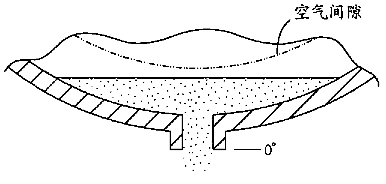
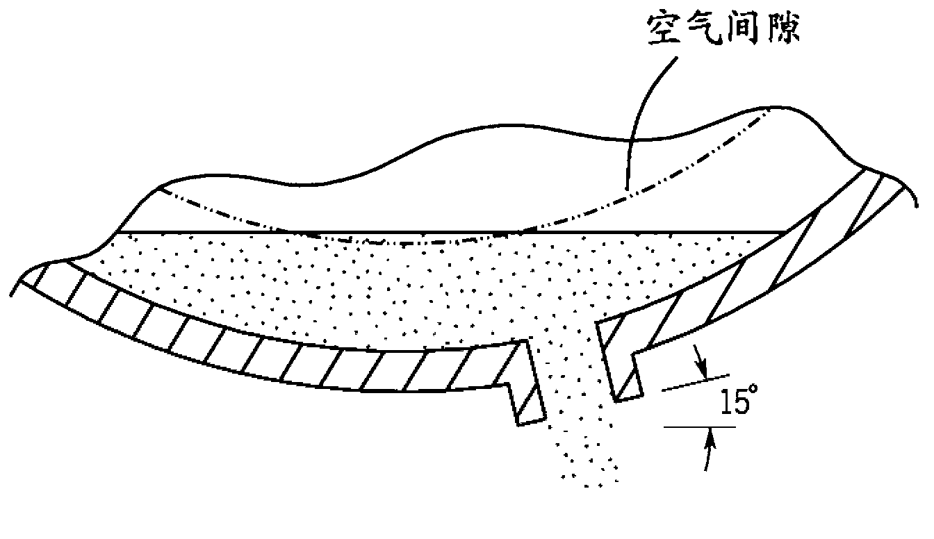
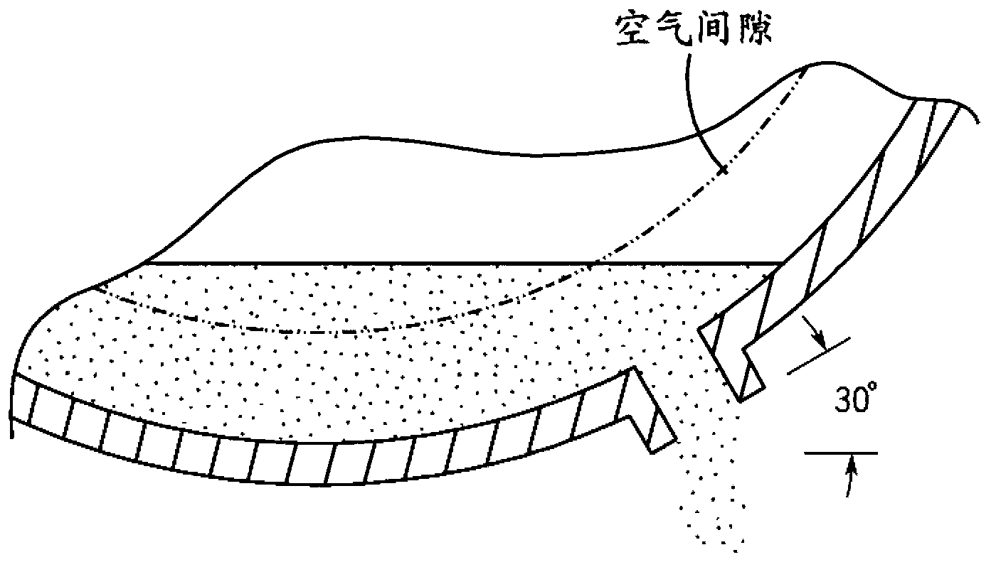
During tilting, the height of the accumulated coolant can increase enough to flood the air gap between the motor stator and the motor rotor, causing negative effects such as relatively large spin losses and / or thermal failure of the motor

Method used


Image

  • Coolant drainage system and method for electric machines
  • Coolant drainage system and method for electric machines
  • Coolant drainage system and method for electric machines

Examples


Embodiment Construction

[0015] Before any embodiments of the invention are explained in detail, it is to be understood that the invention is not limited in its application to the details of construction and the arrangement of parts set forth in the following description or illustrated in the following drawings. The invention is capable of other embodiments and of being practiced or being carried out in various ways. Also, it is to be understood that the phrases and terminology used herein are for the purpose of description and should not be regarded as limiting. The use of "comprising," "comprising," or "having" and variations thereof herein is meant to encompass the items listed thereafter and their equivalents as well as additional items. Unless expressly stated or otherwise limited, the terms "mounted," "attached," "supported," and "coupled," and variations thereof, are used broadly and include direct and indirect mounting, connecting Members, supports, and linkages, and "connected" and "coupled"...


PUM


Abstract

Embodiments of the invention provide a coolant drainage system including a module housing and a drain pan coupled to the module housing. The module housing at least partially defines a machine cavity and includes an inner wall and at least one end cap at least partially enclosing an electric machine within the machine cavity. The coolant drainage system also includes a plurality of drain holes through the module housing and adjacent to the drain pan. The plurality of drain holes provide fluid pathways from the machine cavity to the drain pan.

Description

[0001] related application [0002] This international application claims priority to US Patent Application No. 12 / 897,634, filed October 4, 2010, the entire contents of which are hereby incorporated by reference. Background technique [0003] Traditional methods of cooling electric machines include passing coolant around the outer periphery of the electric machine within a coolant jacket. The coolant extracts heat from the motor's stator. In some machine designs, the level of heat removal is increased by spraying coolant from the coolant jacket directly onto the end turns of the stator. As shown in FIG. 1A , the sprayed coolant is drained toward the bottom of the motor housing due to gravity, and a drain hole is usually located near the bottom of the housing to drain the coolant. However, as shown in FIGS. 1B and 1C , if the motor is tilted backwards, a large amount of coolant can accumulate around the motor within the housing. During tilting, the height of the accumulated...

Claims


Application Information

Patent Timeline
Patent Type & Authority Applications(China)
IPC IPC(8): H02K9/00H02K9/22
CPCH02K9/19H02K5/203H02K1/20H02K9/197H02K9/24H02K5/04H02K2213/03H02K2205/09
Inventor M·D·布拉德菲尔德
Owner REMY TECHNOLOGIES LLC
Why Eureka
Try Eureka