A clamping structure of eva shaping mold

A technology of setting mold and clamping, applied in the field of clamping structure of EVA setting mold, can solve the problems of time-consuming, laborious insertion, extraction, etc., and achieve the effect of shortening opening and closing time, improving production efficiency and simple structure

Inactive Publication Date: 2015-10-28
DONGGUAN XINGTENG FOOTWARE MATERIAL
View PDF3 Cites 1 Cited by
  • Summary
  • Abstract
  • Description
  • Claims
  • Application Information

AI Technical Summary

Problems solved by technology

[0002] Now the clamping structure of the EVA shaping mold is roughly as follows: figure 1 As shown, it includes upper template 1, lower template 2, upper, lower mold 1, 2 are provided with handle 6, and upper and lower mold fixing sleeves 22, 25 corresponding to the difference, and have pin 23, which are inserted when the mold is closed. For the fixed sleeve 22, 25, its function is as follows: figure 2 ﹑ image 3 As shown, put the EVA foam material into the mold cavity of the lower mold, close the cover, lower mold 1, and 2, and insert the locking pin 23. The lower mold fixing sleeve is matched with the hydraulic cylinder lifting rod of the machine 20, so that the upper and lower molds can be heated by the upper and lower heating plates 21.24 at the same time, and the pin 23 is inserted into the upper and lower mold fixing sleeves 22.25 to prevent the upper and lower molds from being opened by mistake when the EVA is heated and foamed. When it is completed, and after the EVA is cooled and shaped, the clamping pin 23 is pulled away, and the upper and lower molds can be opened by pulling the handle 6; the above content actually has the following disadvantages: when closing the mold, the clamping pin 23 needs to be inserted into the The clamping pin 23 needs to be pulled out when the connecting sleeve 22.25 of the upper and lower mold fixing sleeves is opened. However, the clamping pin 23 and the fixing sleeve 22.25 of the upper and lower molds are in close contact with the upper and lower molds. Therefore, it takes a lot of effort to insert and draw distance, and therefore time-consuming, affect the processing speed

Method used


Image

  • A clamping structure of eva shaping mold
  • A clamping structure of eva shaping mold
  • A clamping structure of eva shaping mold

Examples


Embodiment Construction

[0019] The present invention will be further described below with reference to the accompanying drawings.

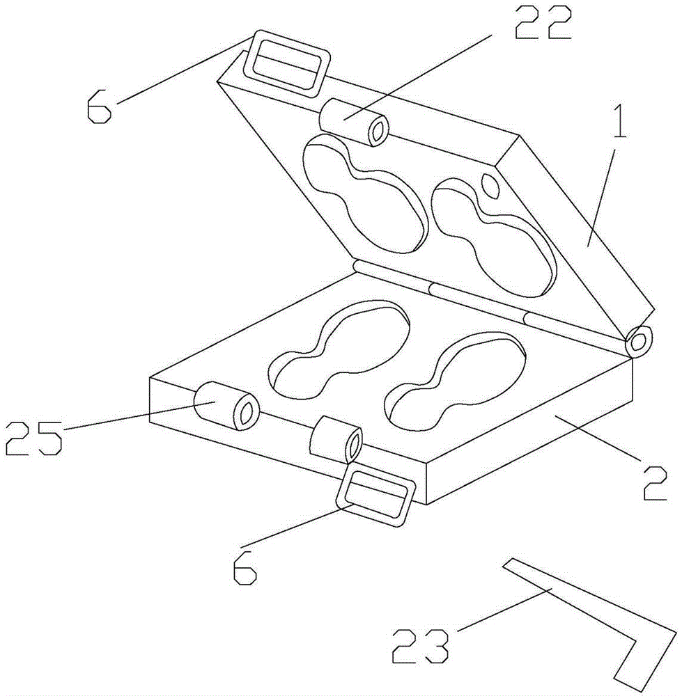
[0020] Such as Figure 4 and Figure 5 As shown, a clamping structure of an EVA shaping mold includes an upper template 1 and a lower template 2, and one end of the upper template 1 and the lower template 2 is respectively provided with an upper and lower mold fixing sleeve 3, and the upper and lower mold fixing sleeves 3 pass through the upper and lower mold fixing pins 4 The other end of the upper template 1 is provided with an opening and closing assembly 5, and the other end of the lower template 2 is provided with a fixing assembly 6 connected with the opening and closing assembly 5.

[0021] Such as Figure 6 The opening and closing assembly 5 shown includes a patrix fixed plate 51, two fixed sleeves 52 are arranged at intervals on the upper mold fixed plate 51, movable fixed hook sleeves 53 are arranged between the two fixed sleeves 52, and the two fixed sleeves...


PUM


Abstract

The invention discloses an EVA fixing die locking structure. The EVA fixing die locking structure comprises an upper die plate and a lower die plate, one ends of the upper die plate and the lower die plate are provided with an upper die fixing sleeve and a lower die fixing sleeve respectively, the upper and lower die fixing sleeves are connected through an upper and lower die fixing pin, the other end of the upper die plate is provided with an opening and closing assembly, and the other end of the lower die plate is provided with a fixed assembly connected with the opening and closing assembly. The EVA fixing die locking structure allows the opening and closing assembly to be connected with the fixed assembly, fixing to be carried out through the pressure of a pressure spring and the connection and separation of a movable positioning hook and a movable positioning hook fixing plate to be controlled through a die opening handle, so the abuses of a traditional die locking structure are avoided. The EVA fixing die locking structure has the advantages of simple structure, substantial shortening of the opening and closing time of the upper die plate and the lower die plate, and production efficiency improvement.

Description

technical field [0001] The invention relates to the technical field of shoemaking, in particular to a clamping structure of an EVA shaping mold. Background technique [0002] Now the clamping structure of the EVA shaping mold is roughly as follows: figure 1 As shown, it includes upper template 1, lower template 2, upper, lower mold 1, 2 are provided with handle 6, and upper and lower mold fixing sleeves 22, 25 corresponding to the difference, and have pin 23, which are inserted when the mold is closed. For the fixed sleeve 22, 25, its function is as follows: figure 2 ﹑ image 3 As shown, put the EVA foam material into the mold cavity of the lower mold, close the cover, lower mold 1, and 2, and insert the locking pin 23. The lower mold fixing sleeve is matched with the hydraulic cylinder lifting rod of the machine 20, so that the upper and lower molds can be heated by the upper and lower heating plates 21.24 at the same time, and the pin 23 is inserted into the upper and...

Claims


Application Information

Patent Timeline
Patent Type & Authority Patents(China)
IPC IPC(8): B29C44/58B29C33/20
Inventor 陈伯雄
Owner DONGGUAN XINGTENG FOOTWARE MATERIAL
Why Eureka
Try Eureka