

Ear thermometer
A thermometer and ear-type technology, applied in radiation pyrometry, sensors, diagnosis, etc., can solve problems such as inability to detect properly, large measurement errors, and inability to ensure measurement status
- Summary
- Abstract
- Description
- Claims
- Application Information
AI Technical Summary
Problems solved by technology
Method used
Image

Examples
no. 1 Embodiment approach
[0034]
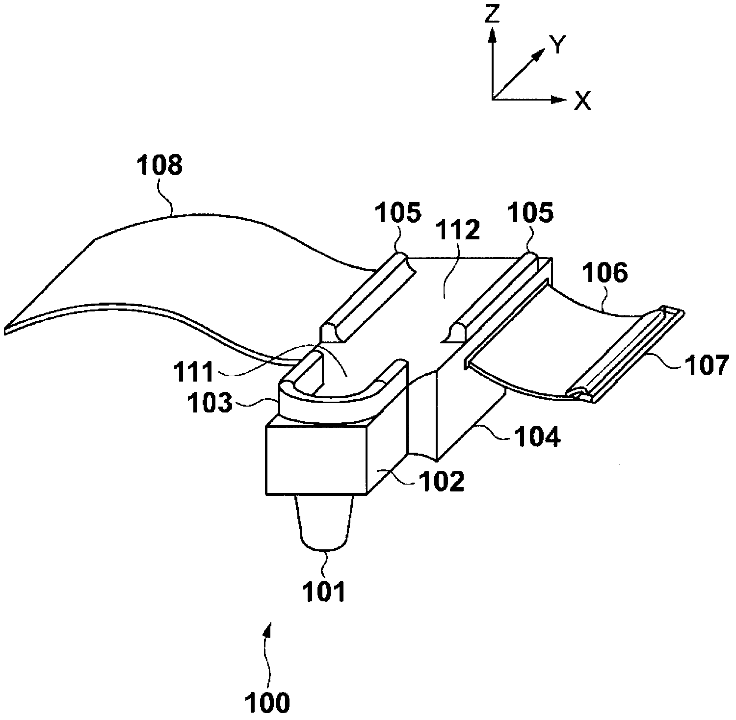
[0035] First, the external configuration of the ear thermometer 100 according to the first embodiment of the present invention will be described. figure 1 It is a figure which shows the appearance structure of the ear thermometer 100 which concerns on 1st Embodiment of this invention.
[0036] exist figure 1 Among them, 101 is a probe part, which is inserted into the ear cavity (external auditory meatus) in order to detect infrared rays radiated from the temperature measurement site (preferably the eardrum and / or its periphery) in the ear cavity. The probe unit 101 has a cylindrical shape with an outer diameter of about 7 mm at the tip so as to be insertable into the ear cavity.
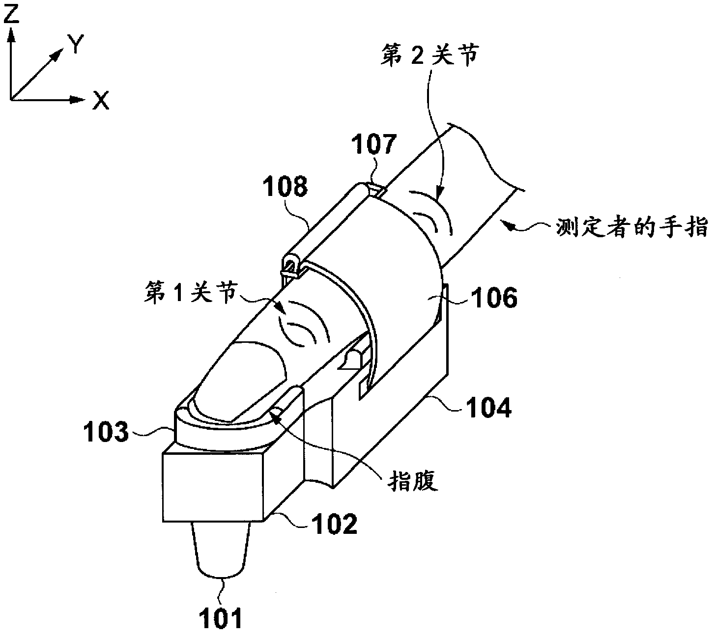
[0037] 102 is a probe support part which supports the probe part 101 on one surface. In addition, on the surface 111 opposite to the surface supporting the probe unit 101, there is provided a finger fixing wall 103 that defines the X-axis direction of the finger when the ear thermomete...
no. 2 Embodiment approach
[0090] In the above-mentioned first embodiment, the structure in which the ear thermometer 100 is mounted on the measurer's fingers using the mounting parts (102 and 104) and the mounting belts 106 and 108 is adopted, but the present invention is not limited thereto. A structure that can be mounted with a fingertip type mounting part is possible. In addition, in the above-mentioned first embodiment, when the ear thermometer 100 is attached, the probe supporting part 102 and the fixing part 104 are located on the same side (that is, the probe part 101 and the fixing part 104 are located on the same side), but the present invention does not Limited to this, for example, the probe unit and the fixing unit may be arranged on different sides. Hereinafter, an ear-type thermometer that has a finger cuff-type mounting portion and is disposed so that the probe portion and the fixing portion are located on opposite sides when mounted will be described.
[0091]
[0092] First, an ext...
no. 3 Embodiment approach
[0118] In the above-mentioned first and second embodiments, the measurement start switch 203 (or 823 ) is arranged on the side surface of the fixing part 104 (or the main body part 803 ). However, when the subject is an infant or the like, fingers other than the finger to which the ear thermometer 100 or 800 is attached are used to press the subject during body temperature measurement. Therefore, it is not always easy to press the measurement start switch 203 (or 823 ) while the probe unit 101 (or 801 ) is inserted into the ear cavity.
[0119] Therefore, in the ear thermometer (referred to as ear thermometer 1200 ) of this embodiment, when the probe unit is reliably inserted into the ear cavity, it is configured to detect this and automatically start measurement. Hereinafter, details of this embodiment will be described.
[0120]
[0121] First, the configuration of the probe unit 1201 of the ear thermometer 1200 will be described. Figure 12 It is a figure which shows th...
PUM
 Abstract
Description
Claims
Application Information