Injection molding apparatus

A technology for injection molding machines and motors, applied in the field of injection molding machines, can solve problems such as loss and achieve the effect of suppressing energy loss

Active Publication Date: 2013-07-03
SUMITOMO HEAVY IND LTD
View PDF3 Cites 4 Cited by
  • Summary
  • Abstract
  • Description
  • Claims
  • Application Information

AI Technical Summary

Problems solved by technology

[0007] However, depending on the motor constituting the injection molding machine, most of the regenerativ

Method used


Image

  • Injection molding apparatus
  • Injection molding apparatus
  • Injection molding apparatus

Examples


Example Embodiment

[0051] Hereinafter, embodiments of the present invention will be described with reference to the drawings.

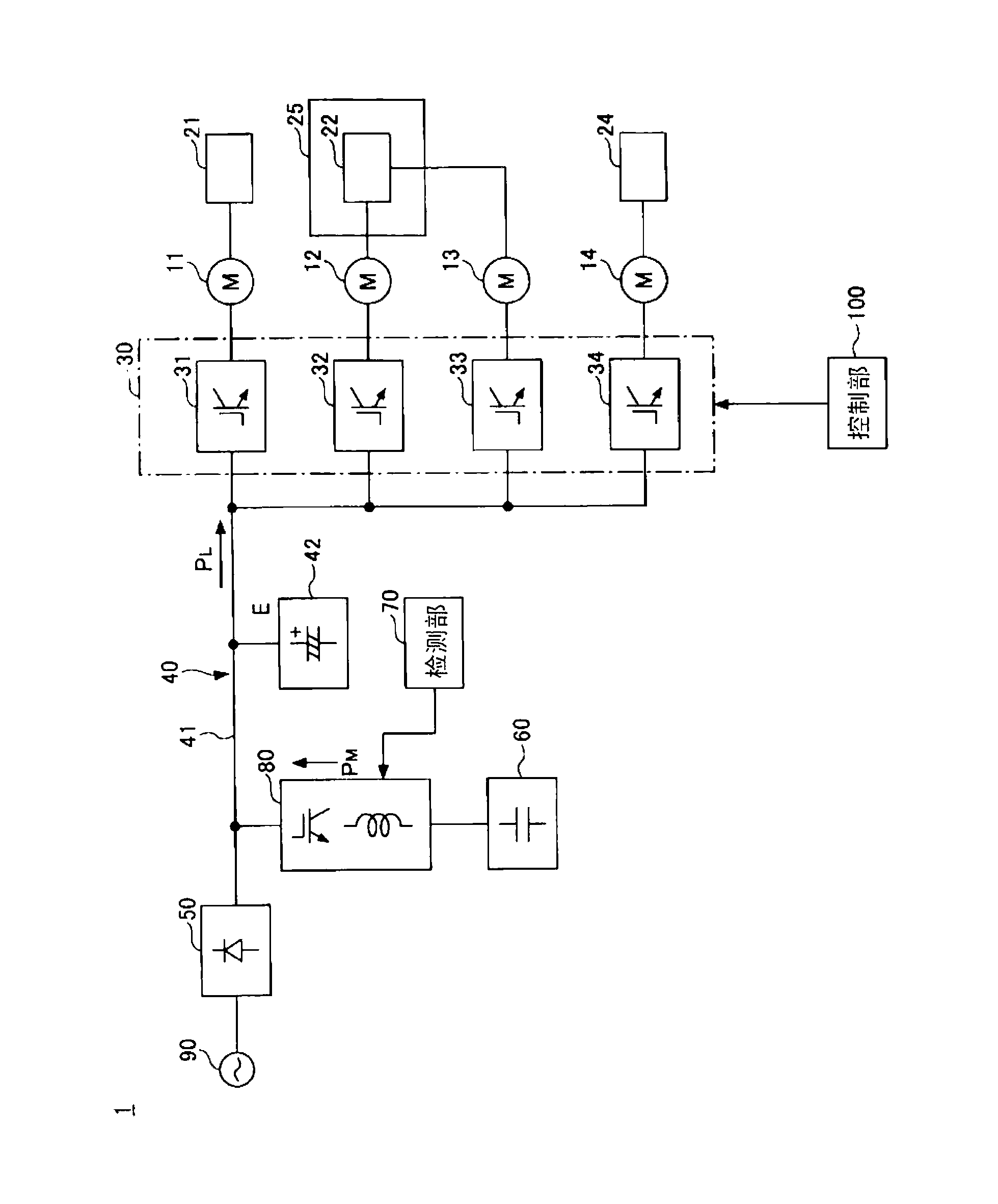
[0052] figure 1 It is a block diagram of the electric injection molding machine 1 which concerns on one Embodiment of this invention.

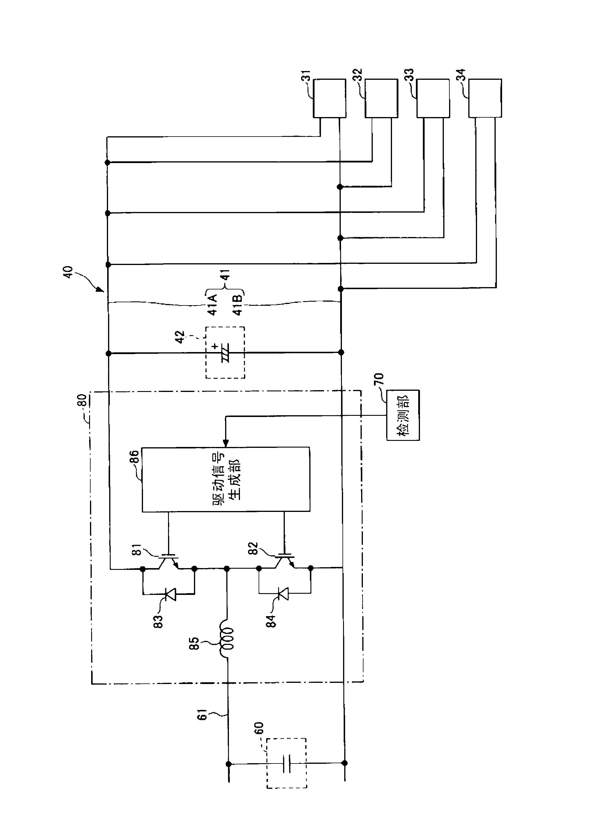
[0053] The injection molding machine 1 includes: a plurality of motors ( figure 1 Four motors 11 to 14 are illustrated in the figure); a drive unit 30 that drives a plurality of motors; a power supply unit 50 that supplies power to the drive unit 30 via a power supply path unit 40 ; a power storage unit 60 ; The unit 40 transmits electric power to the power storage unit 60 . The injection molding machine 1 has a function of charging the power storage section 60 with regenerative energy generated by at least one motor among the plurality of motors via the drive section 30 , the power supply path section 40 , and the power transmission section 80 , and transferring the energy from the power storage section 60 . The released energy is s...


PUM


Abstract

An injection molding apparatus includes plural motors (11-14) including a mold-opening/closing motor (11); a driving unit (30) configured to drive the motors; a feeding path (40); a feeding unit (50) configured to supply power via the feeding path (40) to the driving unit (30); an electric storage (60); a detecting unit (70) configured to detect a driving state of the mold-opening/closing motor (11); and a power transfer unit (80) configured to control power transferred from the feeding path (40) to the electric storage (60) based on the detected driving state of the mold-opening/closing motor (11).

Description

technical field [0001] The present invention relates to an injection molding machine including a plurality of motors including at least a motor for mold opening and closing. Background technique [0002] In order to realize energy saving, there are known injection molding machines which charge the regenerative energy generated by the motor to the power storage unit via the charge and discharge circuit (for example, refer to Patent Documents 1 and 2). [0003] Previous technical literature [0004] Patent Literature [0005] Patent Document 1: Japanese Patent Laid-Open No. 2000-141440 [0006] Patent Document 2: Japanese Patent Laid-Open No. 2001-232672 [0007] However, there is a case where, depending on the motor constituting the injection molding machine, most of the regenerative energy generated by the motor is lost due to the action of transmitting the generated regenerative energy. SUMMARY OF THE INVENTION [0008] An object of the present invention is to provide...

Claims


Application Information

Patent Timeline
IPC IPC(8): B29C45/76
CPCB29C45/7666B29C2045/7673Y02P70/10
Inventor 冈田德高
Owner SUMITOMO HEAVY IND LTD
Why Eureka
Try Eureka