Control device for vehicle driving device

A technology of a driving device and a control device, which is applied to the arrangement of a plurality of different prime movers of a control device and a general power device, a transmission device, etc., can solve the problems of energy consumption and heat generation of the motor, so as to prevent damage and restrain the driving wheel. the slippery effect

Active Publication Date: 2012-10-10
TOYOTA JIDOSHA KK
View PDF5 Cites 5 Cited by
  • Summary
  • Abstract
  • Description
  • Claims
  • Application Information

AI Technical Summary

Problems solved by technology

Therefore, the control device of the vehicle drive device of Patent Document 1 has the problem that, as described above, when the vehicle is started, the wheels are driven only by the electric motor, but when the vehicle driving force generated by the electric motor is equal to or lower than the running resistance In this case, the vehicle remains in a stopped state, and the above-mentioned electric motor will uselessly consume energy (electricity) and generate heat in any case.

Method used


Image

  • Control device for vehicle driving device
  • Control device for vehicle driving device
  • Control device for vehicle driving device

Examples


Embodiment 1

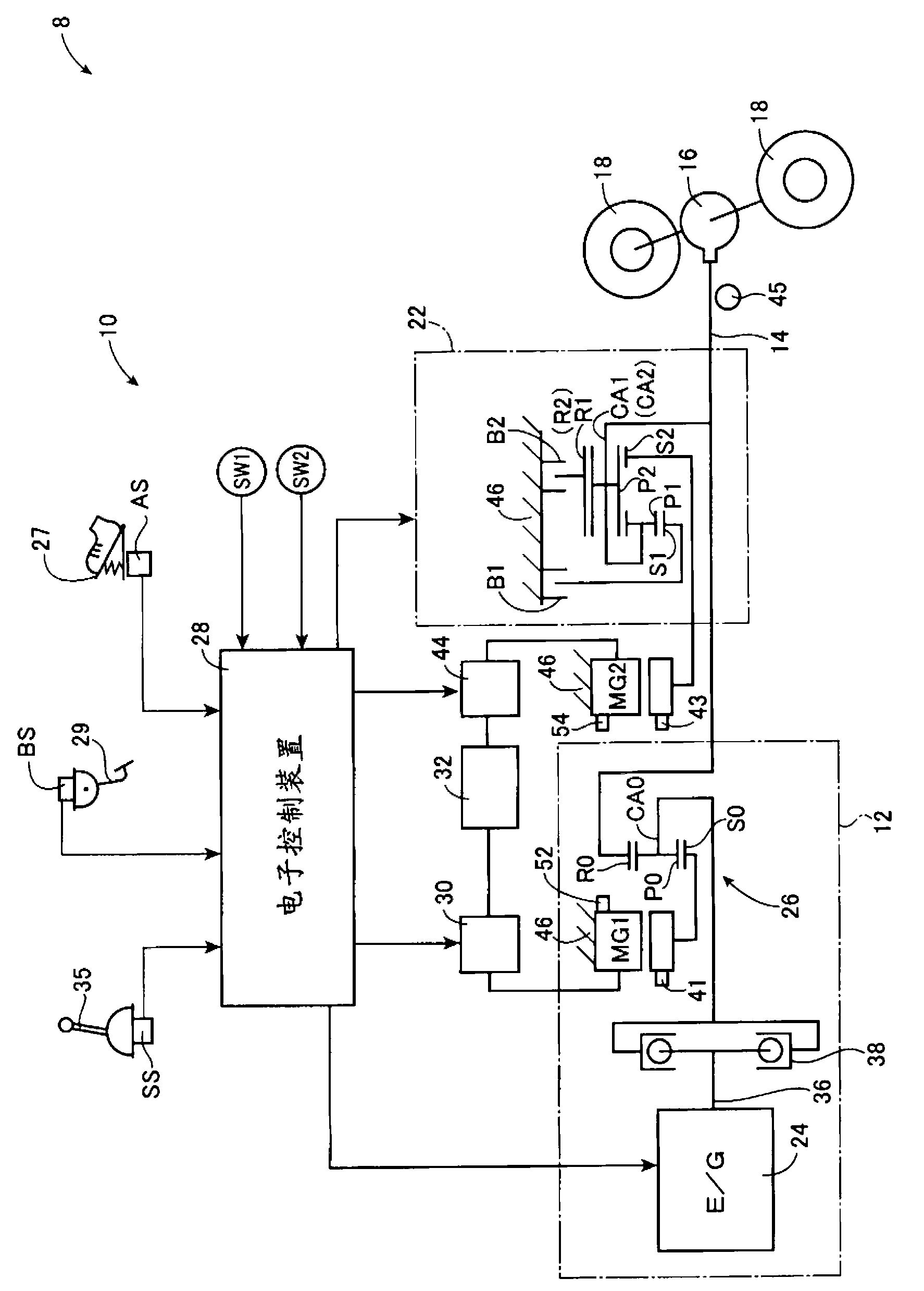
[0042] figure 1It is a schematic configuration diagram illustrating a vehicle drive device 10 used in a hybrid vehicle 8 (hereinafter referred to as "vehicle 8") to which the present invention is applied. figure 1 Among them, the vehicle drive device 10 includes: a first drive source 12 as a main drive source, a wheel-side output shaft 14 (hereinafter referred to as "output shaft 14") functioning as an output member, a differential gear device 16, a second 2 electric motor MG2, automatic transmission 22. In the vehicle drive device 10 , in the vehicle 8 , the torque of the first drive source 12 is transmitted to the output shaft 14 , and the torque is transmitted from the output shaft 14 to the pair of left and right drive wheels 18 via the differential gear unit 16 . . In addition, in this vehicle drive device 10 , the second electric motor MG2 capable of selectively performing power running control for outputting driving force for driving and regeneration control for recov...

Embodiment 2

[0104] In the present embodiment, an example will be described in which the motor torque suppression control is executed when the required drive force Freq once increases or decreases during parking and then increases again. For example, when the vehicle 8 is parked on a sandy road surface where it is difficult to start, the required drive force Freq may repeatedly increase and decrease. Therefore, the above-mentioned situation in which the required drive force Freq increases and decreases once and then increases again occurs. Hereinafter, differences from Embodiment 1 will be mainly described.

[0105] In this embodiment, the start mode switch 208 operated by the driver etc. (refer to Figure 10 ) are installed, for example, near a driver's seat where the driver can easily operate. When the stop start mode switch 208 is operated, the start mode selected when the vehicle 8 is started is selected. The above-mentioned start mode can be released manually, and it is preferable t...


PUM


Abstract

Provided is a control device for a vehicle driving device that can minimize energy loss and useless heat generation when starting-up a vehicle, in a vehicle driving device provided with a motor as the driving source. A motor-torque suppressing and controlling means (98) will conduct a motor-torque suppressing control that will minimize a second motor torque (Tmg2) to be less than an output torque determined by a motor-torque control characteristic (STmg2), when a stopped vehicle (8) is to be started-up, and when the required driving force (Freq) is equal to or less than a required-driving-force criterion value (F1req). Therefore, it will be possible to minimize energy loss and useless heat generation of a second motor (MG2) when starting-up a vehicle, because power consumption by the second motor torque (Tmg2) can be minimized more than when complying with above-mentioned motor-torque control characteristic (STmg2), even when the required driving force (Freq) (degree of accelerator opening (Acc)) is increased within a range in which the vehicle (8) cannot be started-up.

Description

technical field [0001] The present invention relates to a technique of controlling driving force when the vehicle is started in a vehicle having an electric motor as a driving force source. Background technique [0002] Vehicle drive devices including an electric motor as a drive force source, such as hybrid vehicles and electric vehicles, are known. For example, the vehicle drive device disclosed in Patent Document 1 is such a drive device. [0003] The vehicle drive device of Patent Document 1 includes an engine for driving front wheels, a front-wheel electric motor, and a rear-wheel electric motor for driving rear wheels. In addition, the control device of this vehicle driving device basically does not operate the engine when the vehicle is started, and only operates the motor for the front wheels and the motor for the rear wheels (without distinguishing between the motor for the front wheels and the motor for the rear wheels). In the case of a motor, it is just called ...

Claims


Application Information

Patent Timeline
Patent Type & Authority Applications(China)
IPC IPC(8): B60L3/00B60K6/445B60W10/08B60W20/00B60L50/16
CPCY02T10/6239B60L2240/423Y02T10/6217B60L2240/12B60K6/445F16H2037/0873B60W2710/083B60L15/2009B60L15/2063B60W20/00Y02T10/70B60L2240/36B60L11/14Y02T10/7077B60L11/123Y02T10/642B60L3/0061B60W10/08B60L2220/14B60W30/18027Y02T10/72B60L50/61B60L50/16Y02T10/62Y02T10/64Y02T10/7072B60L15/20B60W30/192B60W2510/087
Inventor 大叶充龟谷佳祐
Owner TOYOTA JIDOSHA KK
Why Eureka
Try Eureka