
Current sensor

A current sensor, current technology, applied in the direction of voltage/current isolation, measuring current/voltage, instruments, etc., can solve the problems of reduced measurement accuracy, no mention of the influence of residual magnetic field, residual magnetic body, etc., to achieve improved measurement accuracy, Excellent current detection characteristics, effect of reducing residual magnetic field

Inactive Publication Date: 2013-07-03
TDK CORPARATION
View PDF7 Cites 16 Cited by
  • Summary
  • Abstract
  • Description
  • Claims
  • Application Information

AI Technical Summary

Problems solved by technology

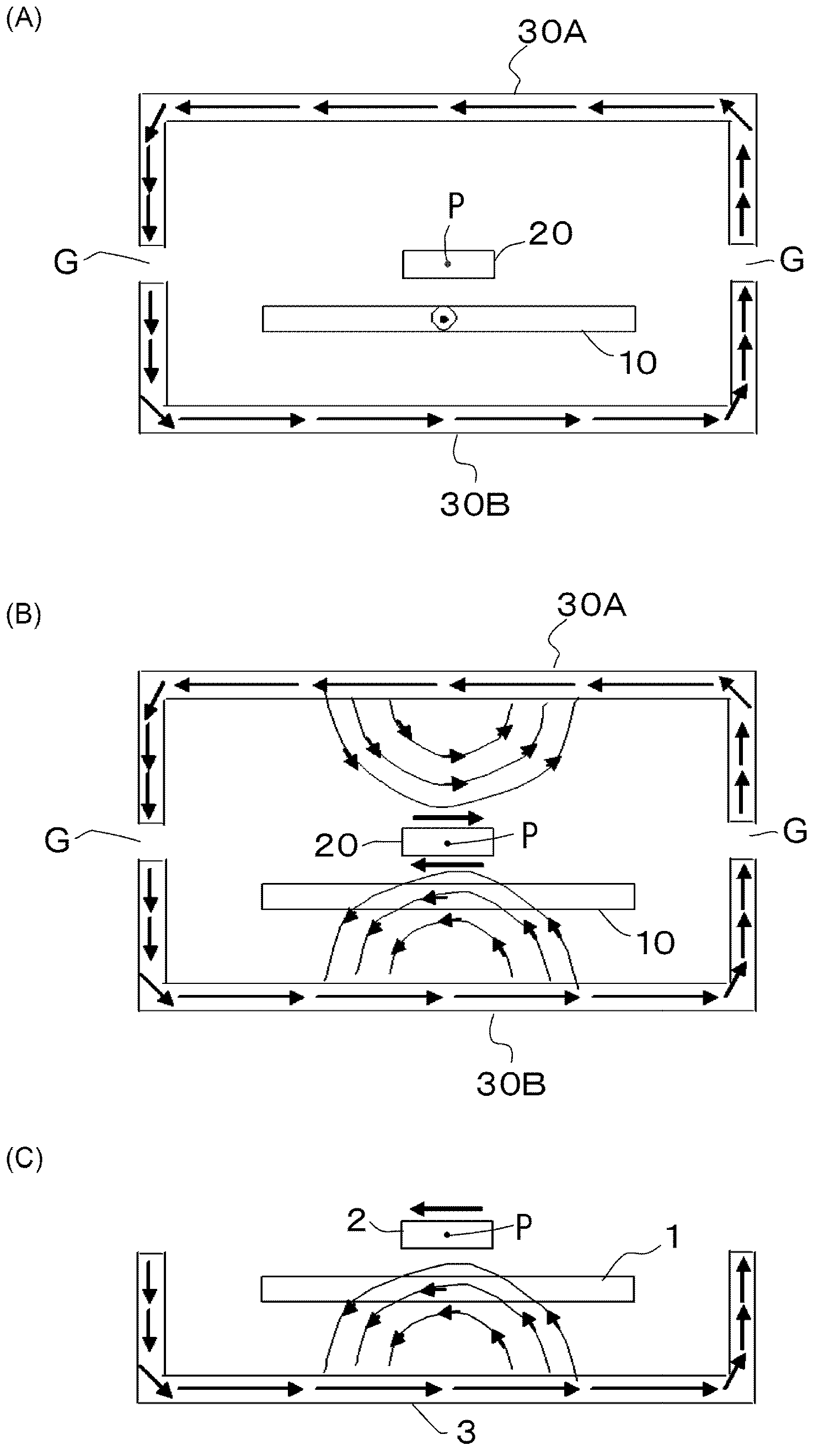
That is, after the current to be measured flows to the bus, even if the current of the bus becomes 0 ampere, the residual magnetic field generated by the magnetic material remains, and there is a problem that the measurement accuracy decreases when the bus is not energized (0 ampere).
In addition, in the conventional examples, there is no mention of countermeasures against the influence of the residual magnetic field caused by the hysteresis of the magnetic material for magnetic shielding.

Method used


Image

  • Current sensor
  • Current sensor
  • Current sensor

Examples


Embodiment Construction

[0045] Below, while referring to the attached Figure 1 Preferred embodiments of the present invention will be described in detail. In addition, the same or equivalent constituent elements, members, processes, etc. shown in each drawing are denoted by the same reference numerals, and overlapping descriptions are appropriately omitted. In addition, the embodiment is not to limit the invention but to illustrate, and all the features or combinations thereof described in the embodiment are not necessarily limited to the essence of the invention.

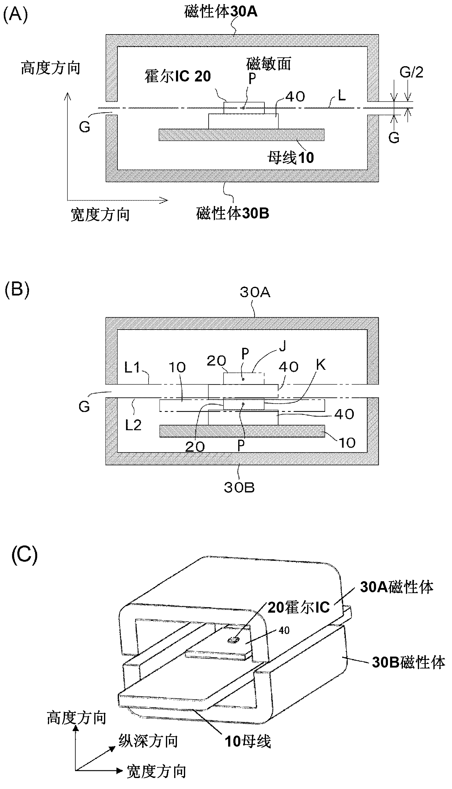
[0046] figure 1 It is the first embodiment of the current sensor according to the present invention, which has a bus bar 10 which is a conductor through which the current to be measured flows, and a magnetosensitive element which is fixedly arranged relative to the bus bar (current conducting part) 10 via an insulating substrate 40 Hall IC 20 , and a pair of first and second cross-sectional U-shaped magnetic bodies 30A, 30B that magne...


PUM


Abstract

A current sensor has first (30A) and second magnetic bodies (30B) for magnetic shielding opposed to each other, and a bus bar (10) and a Hall IC (20) disposed between the magnetic bodies. The magnetic bodies (30A, 30B) are magnetized in directions opposite to each other when a current flows through the bus bar (10), and the Hall IC (20) is disposed at a position at which a magnetic field applied to the Hall IC (20) is weakened by a magnetic field generated by magnetization of the first magnetic body (30A) and a magnetic field generated by magnetization of the second magnetic body (30B).

Description

technical field [0001] The present invention relates to a current sensor for measuring battery current or motor drive current of, for example, a hybrid vehicle or an electric vehicle, and more particularly to a current sensor for measuring current flowing to a bus using a magnetic sensor such as a Hall element. Background technique [0002] As a current sensor that detects the current (current to be measured) flowing to the bus bar in a non-contact state using a magnetic sensor such as a Hall element, a ring-shaped magnetic core with a gap and a A magnetic proportional current sensor with a magneto sensitive element placed in the air gap. In addition, the electric motors of hybrid vehicles and electric vehicles in recent years are driven by three-phase alternating current whose phases are shifted by 120 degrees. Therefore, three bus bars for three-phase alternating current (U phase, V phase, W phase) are used for electrical connection with the outside. In order to reduce t...

Claims


Application Information

Patent Timeline
Patent Type & Authority Applications(China)
IPC IPC(8): G01R19/00
CPCG01R15/207G01R15/14
Inventor 宫腰高明柏木孝夫平野裕幸福冈诚二
Owner TDK CORPARATION
Learn More