Current sensor
a current sensor and sensor technology, applied in the field of current sensor, can solve problems such as the reduction of measurement accuracy, and achieve the effects of reducing current measurement errors, improving measurement accuracy, and reducing hysteresis
- Summary
- Abstract
- Description
- Claims
- Application Information
AI Technical Summary
Benefits of technology
Problems solved by technology
Method used
Image
Examples
first embodiment
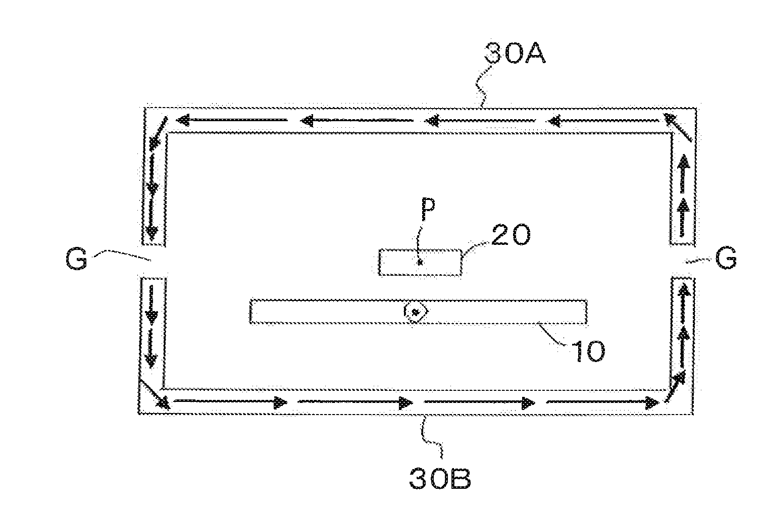
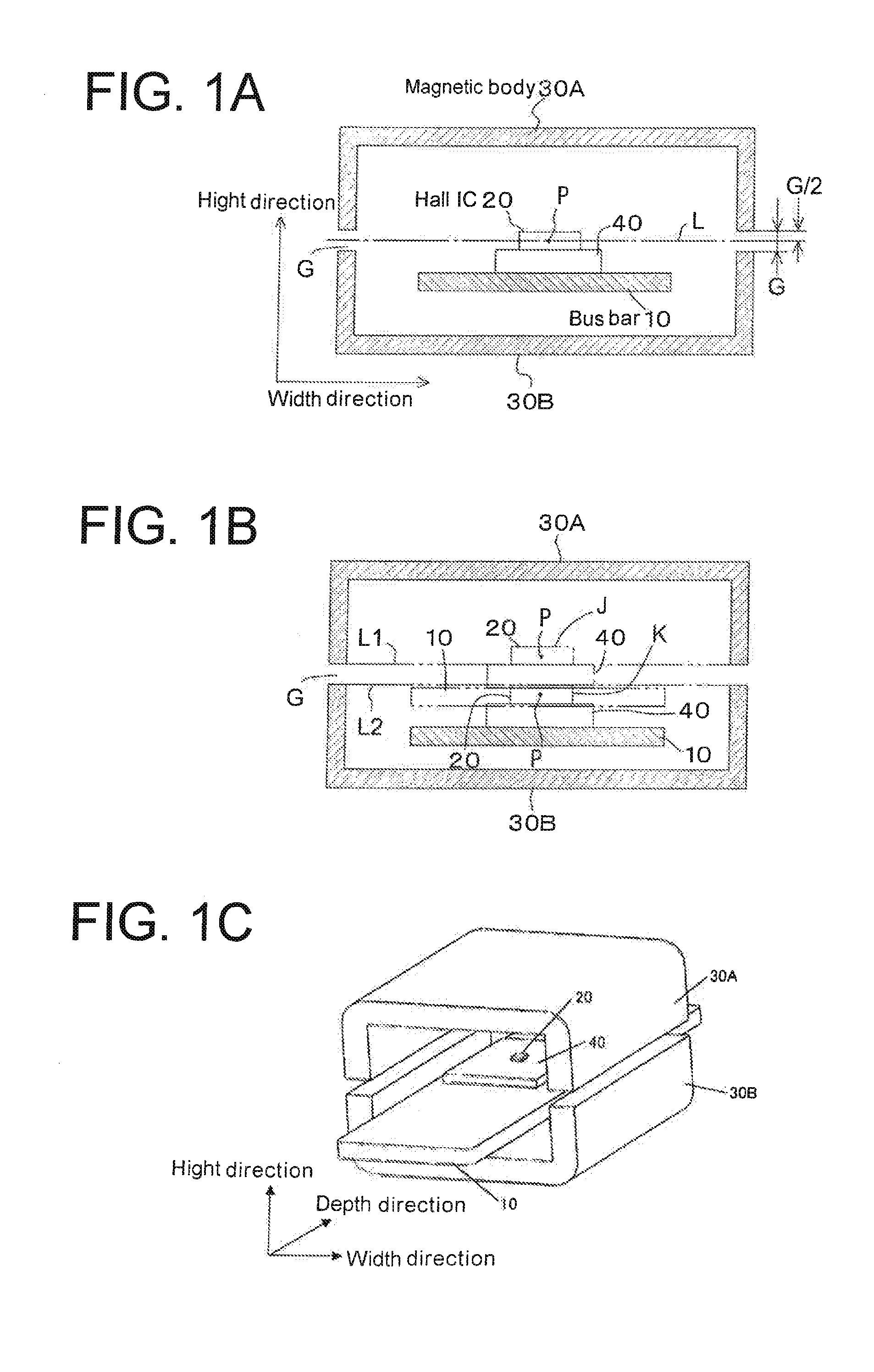
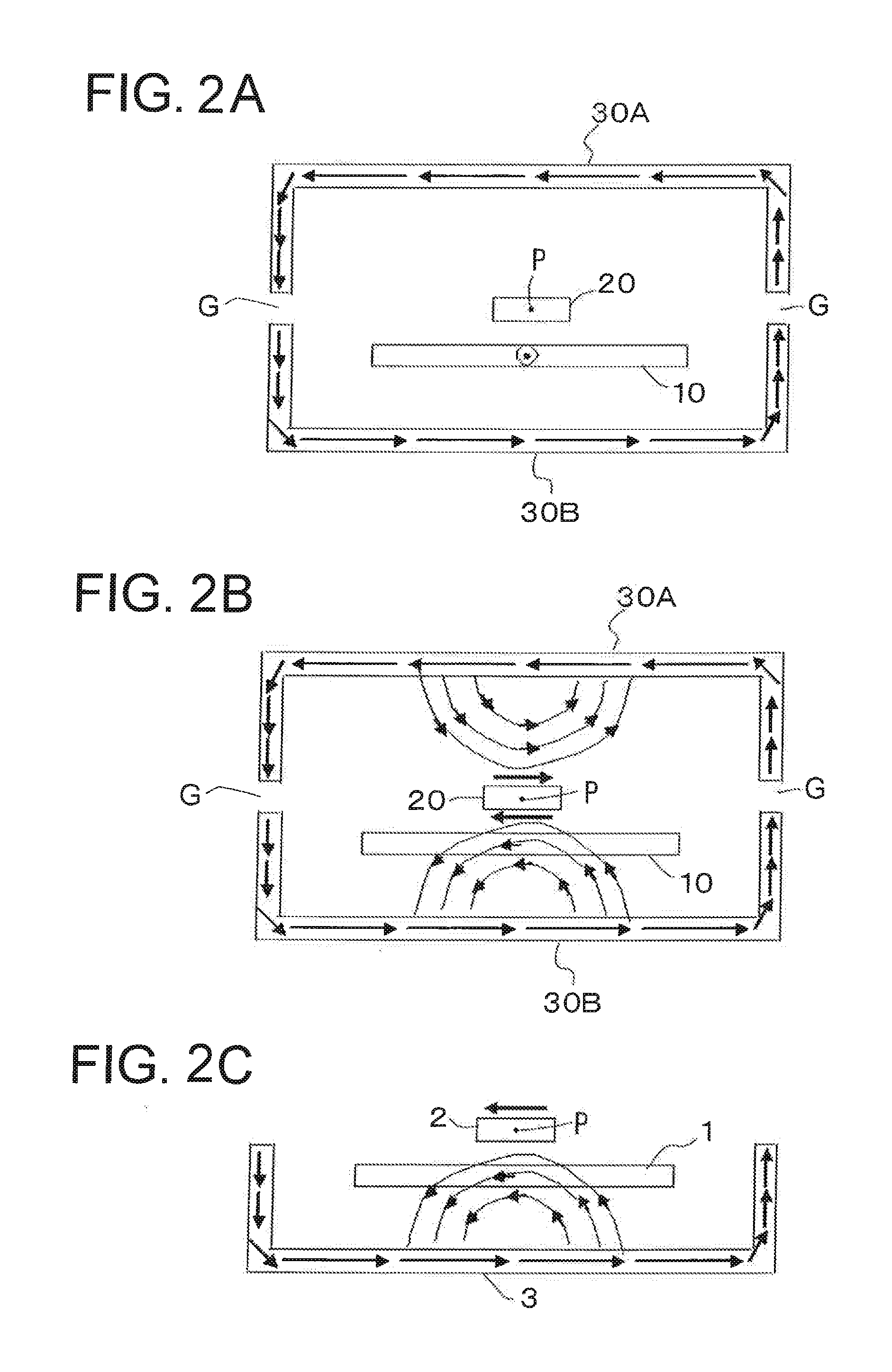
[0040]FIG. 1A to 1C show a current sensor according to the present invention and the current sensor has a bus bar (current conducting member) 10 that is a conductor through which a measured current flows, a Hall IC 20 acting as a magnetic sensitive element fixedly disposed via an insulating substrate 40 on the bus bar 10, and a pair of first and second U-shaped cross-sectional magnetic bodies 30A and 30B magnetically shielding the Hall IC 20. The both end edges of the pair of the first and second U-shaped cross-sectional magnetic bodies 30A and 30B are opposed to each other with respective air gaps (magnetic gaps) G therebetween. In FIG. 1A, the height direction and the width direction are defined by arrows.
[0041]The bus bar 10 is in a flat-plate shape (e.g., a cupper plate) and the Hall IC 20 is fixedly disposed via the insulating substrate 40 on a wide principal surface of the bus bar 10 such that a magnetic field generated by a current flowing through the bus bar 10 (magnetic fie...
second embodiment
[0057]Since magnetic body portions opposed across the Hall IC 20 in the up-and-down direction are removed as the opening holes 31 in the case of FIG. 5, the effect of magnetic fields exerted from the magnetic body portions facing the Hall IC 20 squarely in the up-and-down direction is reduced and, as a result, fluctuations are suppressed in a generated magnetic field at the position of the magnetic sensitive surface of the Hall IC 20 due to upward and downward positional shifts of the first and second magnetic bodies 30A and 30B from each other. This will be described with reference to FIGS. 7A and 7B and FIGS. 8A and 8B.
[0058]FIG. 7A to FIG. 7D show the presence of a positional shift between the first and second magnetic bodies 30A and 30B in the embodiments and FIGS. 7A, 7B, 7C, and 7D are front cross-sectional views when both have no positional shift, when the first magnetic body 30A is positionally shifted upward, when the first magnetic body 30A is positionally shifted to the r...
third embodiment
[0062]Since magnetic body portions opposing across the Hall IC 20 in the width direction are removed as the cutout portions 32 in the case of FIG. 6, the effect of magnetic fields exerted from the magnetic body portions facing the Hall IC 20 squarely in the width direction is reduced and, as a result, fluctuations are suppressed in a generated magnetic field at the position of the magnetic sensitive surface of the Hall IC 20 due to leftward and rightward (lateral) positional shifts of the first and second magnetic bodies 30A and 30B from each other. This will be described with reference to FIGS. 7A to 7D and FIGS. 8A to 8C.
[0063]If the third embedment of FIG. 6 causes a lateral shift to the right or left as shown in FIGS. 7C and 7D, a difference ΔmT between no shift and rightward shift (or leftward shift) is −0.014 as shown in FIG. 8C and it can be seen that the difference is reduced from the difference ΔmT of −0.039 between no shift and rightward shift (or leftward shift) of FIG. 8...
PUM
 Abstract
Description
Claims
Application Information
 - R&D
- Intellectual Property
- Life Sciences
- Materials
- Tech Scout
- Unparalleled Data Quality
- Higher Quality Content
- 60% Fewer Hallucinations
Browse by: Latest US Patents, China's latest patents, Technical Efficacy Thesaurus, Application Domain, Technology Topic, Popular Technical Reports.
© 2025 PatSnap. All rights reserved.Legal|Privacy policy|Modern Slavery Act Transparency Statement|Sitemap|About US| Contact US: help@patsnap.com


