Positioning device of solar energy receiving system

A positioning device and receiving system technology, applied in the direction of position/direction control, control/regulation system, non-electric variable control, etc., can solve the problems of poor stability, low running accuracy, unrealistic motor drive, etc., to achieve low cost, Easy to control effects

Active Publication Date: 2013-07-03
HANGZHOU SANHUA RES INST CO LTD
View PDF7 Cites 2 Cited by
  • Summary
  • Abstract
  • Description
  • Claims
  • Application Information

AI Technical Summary

Problems solved by technology

The disadvantages of this positioning device are:
[0008] 1) The rotation range is limited. When the sun's rays are close to the level in the morning or evening, the driving force arm of the hydraulic device is limited, making it difficult for the solar receiving plate to move to the corresponding position, and the solar receiving plate can only be within a certain range track the sun;
[0009] 2) The mechanism of the motor-driven positioning device has low operating accuracy and poor stability;
[0010] 3) The power of the motor is limited. For a solar system with a large size and weight, it is not realistic to use a motor drive

Method used


Image

  • Positioning device of solar energy receiving system
  • Positioning device of solar energy receiving system
  • Positioning device of solar energy receiving system

Examples


specific Embodiment approach

[0042] In this manual:

[0043] 1) The control device does not belong to the invention point of the present invention, so it will not be explained in detail in this specification.

[0044] 2) The ground and the roof refer to the location where the solar system is fixed, and are not limited to this, and are only used as a guide.

[0045] 3) The hydraulic cylinder includes a hydraulic cylinder liner and a piston or guide rod slidingly installed in the cylinder liner. In this specification, the cylinder liner is defined as the fixed part, and the movable guide rod or piston is defined as the action part.

[0046] 4) Horizontal direction: the direction parallel to the ground; height direction: the direction perpendicular to the ground.

[0047] 5) Dead point: The hydraulic cylinder of the second hydraulic system and the push rod connected to it are in a straight line.

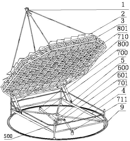
[0048] Such as figure 1 , figure 2 In the shown solar system, the solar system includes a solar positioning...

Embodiment 1、2、3

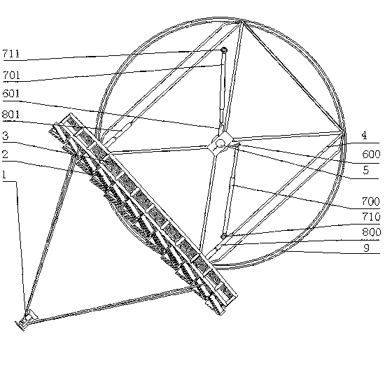
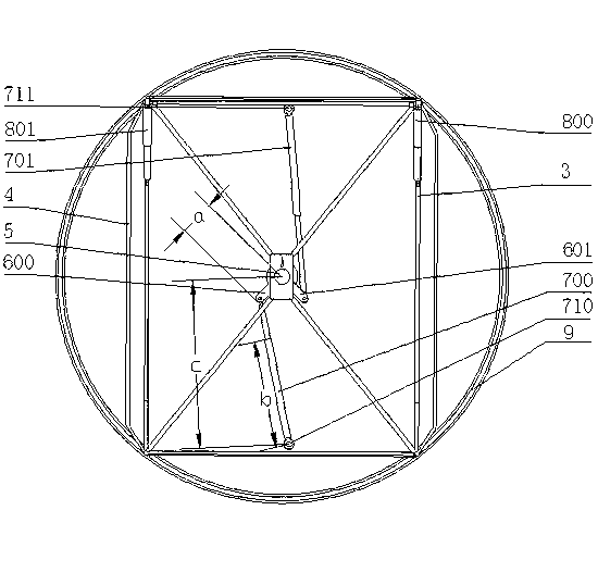
[0082] Such as Figure 1 to Figure 9 The illustrated second hydraulic system includes two hydraulic cylinders: a first hydraulic cylinder 700 and a second hydraulic cylinder 701 .

[0083] The central shaft 5 is provided with fixedly installed push rods: the first push rod 600 and the second push rod 601, and the first ends of the first hydraulic cylinder 700 and the second hydraulic cylinder 701 are connected with the first push rod 600 and the second push rod respectively. The rod 601 is hinged. Two fixed seats are fixedly installed on the ground or on the roof: the first fixed seat 710 and the second fixed seat 711, and the second ends of the first hydraulic cylinder 700 and the second hydraulic cylinder 701 are connected with the first fixed seat 710 and the second fixed seat respectively. The fixing seat 711 is hinged.

[0084] During specific implementation, the hydraulic cylinders of the second hydraulic system can apply pushing force to the turntable at the same time...


PUM


Abstract

The invention relates to a positioning device of a solar energy receiving system. The solar energy receiving system comprises the positioning device and sunlight receiving boards fixedly mounted on the positioning device, wherein the positioning device comprises a rotary piece, a rotating frame and a second hydraulic system; the rotary piece rotates by taking an axis of the rotary piece as an axle; the rotating frame is fixedly connected with the rotary piece, and rotates with the rotary piece; the sunlight receiving boards are driven to rotate with the rotating frame during rotation; the second hydraulic system is used for driving the rotating frame to rotate by taking the axis of the rotary piece as the axle, comprises at least two hydraulic cylinders, and is provided with fixing seats that correspond to the hydraulic cylinders respectively and are fixedly mounted on the ground or a roof; first ends of the hydraulic cylinders are articulated with the fixing seats respectively; and second ends of the hydraulic cylinders are articulated with the rotary piece.

Description

technical field [0001] The invention relates to the field of new energy, and more specifically, relates to a positioning device for a solar energy receiving system. Background technique [0002] In a dish solar system or a photovoltaic solar system that performs two-dimensional tracking, the tracking accuracy of the positioning device to the sun's azimuth is an important factor that affects its work efficiency and energy utilization. For example, compared with ordinary fixed photovoltaic solar energy systems, if a solar photovoltaic panel with the same area can always be perpendicular to the sun's rays, its energy utilization efficiency will be greatly increased. For the dish solar system, the tracking accuracy of the positioning device to the position of the sun is the basic premise of its work. [0003] In the current common solar energy systems, there are usually two types of methods for driving the positioning device to track the sun (dish condenser or photovoltaic pane...

Claims


Application Information

Patent Timeline
Patent Type & Authority Applications(China)
IPC IPC(8): G05D3/00
Inventor 韩延明陈俊
Owner HANGZHOU SANHUA RES INST CO LTD
Why Eureka
Try Eureka