
Methods and apparatuses for generating patterns on workpieces

A workpiece and tool technology, applied in the field of equipment used to generate patterns on workpieces, can solve problems such as sacrificing speed

Active Publication Date: 2013-07-17
MICRONIC LASER SYST AB
View PDF11 Cites 10 Cited by
  • Summary
  • Abstract
  • Description
  • Claims
  • Application Information

AI Technical Summary

Problems solved by technology

Thus, patterning instruments have traditionally sacrificed speed to achieve the requisite accuracy of pick and place machines

Method used


Image

  • Methods and apparatuses for generating patterns on workpieces
  • Methods and apparatuses for generating patterns on workpieces
  • Methods and apparatuses for generating patterns on workpieces

Examples


Embodiment Construction

[0030] Now, the example embodiments will be described more fully with reference to the accompanying drawings in which some example embodiments are shown. In the drawings, the thickness and sections of layers are exaggerated for clarity. Similar reference numerals in the drawings indicate similar elements.

[0031] Detailed illustrative embodiments are disclosed herein. However, the specific structural and functional details disclosed herein are only representative for the purpose of describing example embodiments. The example embodiments may be implemented in many alternative forms, and they should not be interpreted as being limited to only the example embodiments set forth herein. The example embodiments are to cover all modifications, equivalents, and alternatives falling within an appropriate range.

[0032] Although the terms first, second, etc. may be used herein to describe various elements, these elements should not be limited by these terms. These terms are only used t...


PUM


Abstract

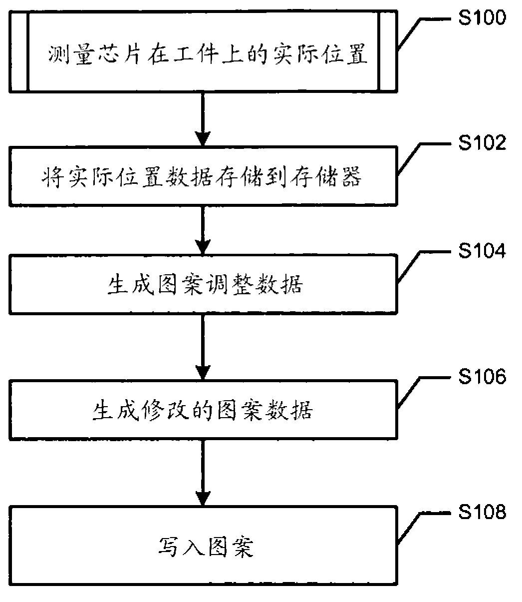
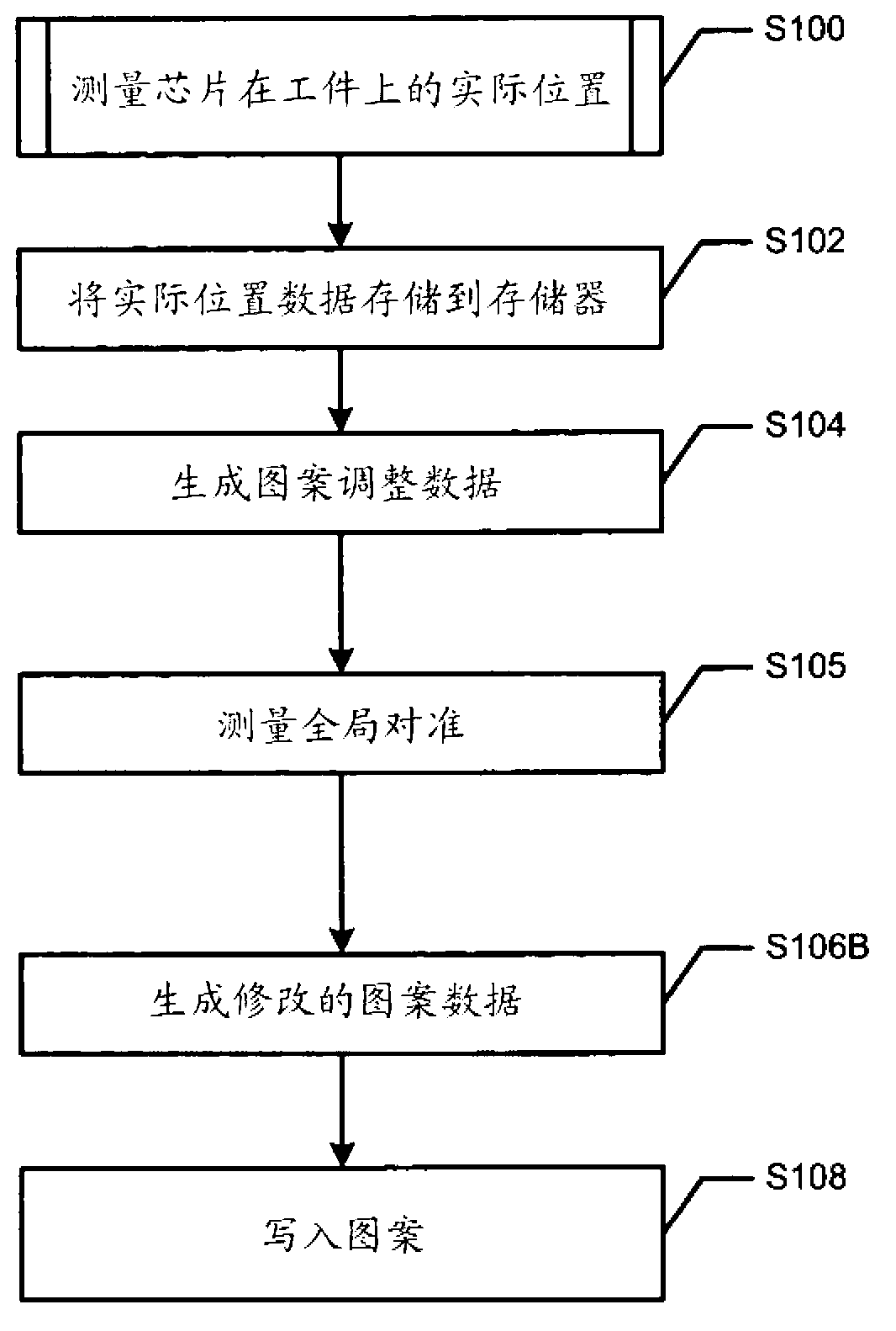
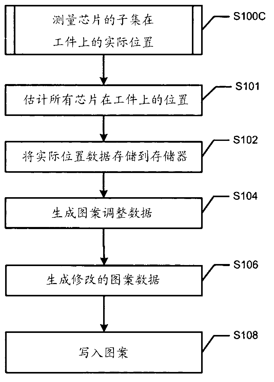
A pick-and-place tool configured to pick and place at least one die on a workpiece includes a mounting head. The mounting head includes a die position determining unit configured to one of measure and detect an actual position of at least one die during a time between the placement of the at least one die on the workpiece and the picking up of a subsequent die for placement on the workpiece.

Description

[0001] (Multiple) cross references to related applications [0002] This patent application claims the benefit of U.S. Provisional Application No. 61 / 383,317 filed on September 15, 2010. Technical field [0003] Example embodiments relate to a method and apparatus for performing pattern alignment on a die, and a method and apparatus for generating a pattern on a workpiece. Background technique [0004] In the packaging and assembly industry, stacked structures have become more common. However, generally, it is relatively difficult to accurately match the structure on the subsequent layer with the structure on the previous layer. [0005] An example of a process that requires relatively accurate matching of structures is stacking chips on top of each other, where the second chip and the first chip must be aligned relatively accurately to produce sufficient contact between the two chips. [0006] Another example is fan-out or embedded chip processing, where the first structure is compos...

Claims


Application Information

Patent Timeline
Patent Type & Authority Applications(China)
IPC IPC(8): H01L21/68H05K13/04H01L21/683H01L21/67
CPCH01L21/6838H01L21/67144H01L21/681H01L21/67132H05K13/0413H05K13/0815Y10T29/53Y10T29/53061Y10T29/53178H05K13/0404H05K2203/0528
Inventor M.瓦尔斯坦P-E.古斯塔夫森
Owner MICRONIC LASER SYST AB
Learn More