Cross Lapper

A cross-lapper and deflecting roller technology, applied in the direction of rolling mechanism, textile and papermaking, fiber processing, etc., can solve the problem of not having an independent cover tape, and achieve the effect of avoiding interference

Active Publication Date: 2015-12-09
TRUTZSCHLER NONWOVENS
View PDF9 Cites 18 Cited by
  • Summary
  • Abstract
  • Description
  • Claims
  • Application Information

AI Technical Summary

Problems solved by technology

However, this crosslapper does not have a separate cover belt that mates with the feed belt

Method used


Image

  • Cross Lapper
  • Cross Lapper
  • Cross Lapper

Examples


Embodiment Construction

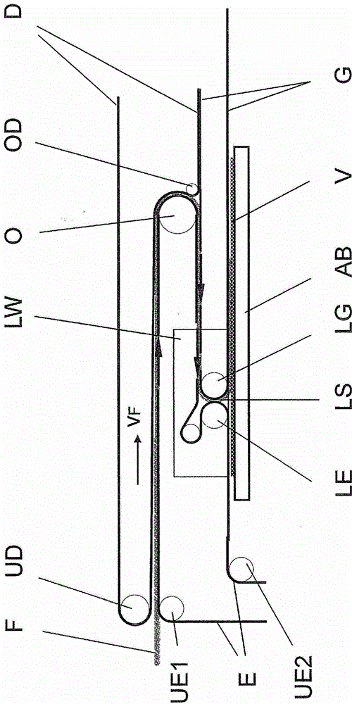
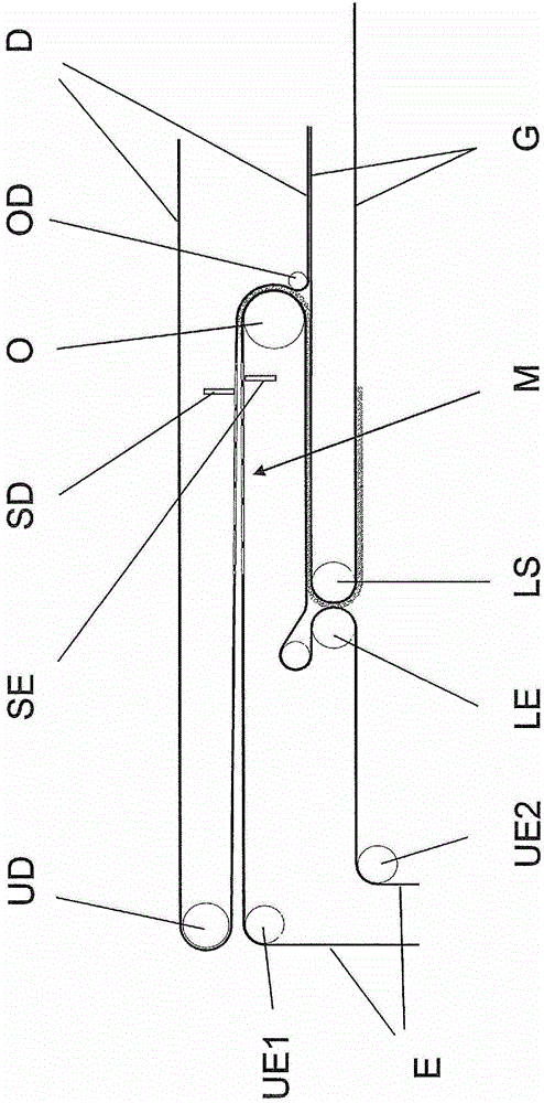
[0034] The pile F is conveyed on an endless endless feed belt E to a crosslapper, only the main components of which are shown in the figure. The direction of travel of the pile F and the feed belt E is indicated by arrows. The pile F moves at a speed vF at which the feed belt E circulates. The feed belt E is tensioned and guided around deflection rollers UE1 , UE2 and also around a first deflection roller O which is arranged in a carriage OW (not shown in detail) in connection with the upper The carriage OW performs periodic reciprocating motion together.

[0035] Above the feed belt E, the cover belt D runs at the same speed and in the opposite direction of rotation. In the area of ​​the tuft feed, the cover web D is guided around the deflection roller UD and runs substantially parallel to the feed belt E (or at an acute angle relative to it) towards the first deflection roller O of the upper carriage OW. On the way between the deflection roll UD and the deflection roll O,...


PUM


Abstract

The invention relates to a cross-lapper and to a method for forming a nonwoven fabric made of a plurality of pile layers, consisting of an continuously revolving feed belt (E), a counter belt (D) continuously revolving at the same speed in the opposite direction, as well as an additional counter belt (G), wherein the pile (F) to be laid is first conveyed between a feed belt and cover belt (E, D) to a movable upper carriage (OW), which comprises a first deflection roller (O) for the feed belt (E), and is transferred there to the counter belt (G), wherein the feed and counter belts (E,G) are guided around two adjacent laying rollers (LE, LG) of a laying carriage (LW) which form a laying gap, and the laying carriage (LW) is movably mounted transversely to and above a discharge belt (AB) receiving the nonwoven fabric to be laid and moves back and forth periodically. According to the invention, the cover belt (D) is guided jointly with the feed belt (E) around a partial circumference of the first deflection roller (O).

Description

technical field [0001] According to the preambles of the device claim and the method claim respectively, the invention relates to a crosslapper. Background technique [0002] EP1870499B1 shows a general type of crosslapper. Such a crosslapper is formed by an endless rotary infeed belt on which the pile to be laid is transported into the laying device. The feed belt also has associated therewith a cover belt which covers the pile and runs in the opposite direction to the feed belt at the same rotational speed. The pile is held between the feed belt and the cover belt. An upper carriage is supported for movement in the conveying direction of the supplied tuft and for periodic reciprocating movement, said upper carriage comprising deflection rollers for the cover belt and the feed belt. The pile initially held between the feed belt and the cover belt is then transferred to the counter belt and thereafter held between the counter belt and the feed belt. The counter belt move...

Claims


Application Information

Patent Timeline
Patent Type & Authority Patents(China)
IPC IPC(8): D01G25/00
CPCD01G25/00
Inventor 伯恩哈德·吕贝纳克萨沙·霍尔茨施奈德
Owner TRUTZSCHLER NONWOVENS
Why Eureka
Try Eureka