Shield ball

A technology of shielding balls and fixed shielding, which is applied in the direction of shielding devices, can solve the problems of time-consuming installation, inconvenient assembly operation, and high cost, and achieve the effects of simple and convenient operation, solving shielding problems, and meeting the requirements of insulation tests

Active Publication Date: 2015-06-03
STATE GRID CORP OF CHINA +1
View PDF4 Cites 0 Cited by
  • Summary
  • Abstract
  • Description
  • Claims
  • Application Information

AI Technical Summary

Problems solved by technology

[0002] The two ends of the CT unit of the 126kV GIS three-phase common box type current transformer are insulators. During the insulation test, the center conductor of the insulator needs to be shielded. Currently, the two ends of the insulator are connected to the connecting cylinder and the bushing to achieve shielding. Yes, this shielding method is very inconvenient to assemble and operate in the actual test, and the installation is time-consuming and costly

Method used


Image

  • Shield ball
  • Shield ball
  • Shield ball

Examples


Embodiment Construction

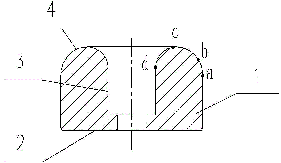
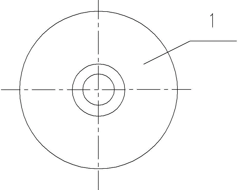
[0013] figure 1 , figure 2 Shown is an embodiment of the shielding ball of the present invention, which includes a shielding ball body 1 in the shape of a rotating cylinder. On the axis of the shielding ball body, there is a stepped installation through hole extending along the axis. The large aperture of the installation through hole The section is the counterbore 3 used to sink into the head of the fastener fixing the shielding ball. On the longitudinal section of the shielding ball body, the hole surface at the opening end of the counterbore and the side surface of the shielding ball body pass through a transition arc tangent to the two surfaces. Surface 4 is connected; the end face of the shielding ball body away from the counterbore is the mounting surface 2 used to cooperate with the workpiece to be shielded. The intersection part is a rounded structure.

[0014] In this embodiment, the transition arc surface 4 is formed by connecting three sections of arcs ab, bc and...


PUM


Abstract

The invention relates to a shield ball, which comprises a shield ball body shaped like a gyrating column, wherein a stepped mounting hole is formed in the axis of the shield ball body in an extending manner in the axis direction; a sinking hole for sinking and fixing the head of a fastener of the shield ball is formed in a large hole neck section of the mounting hole. A hole surface at the opening end of the sinking hole and a side surface of the shield ball body are connected onto a longitudinal cross-section of the shield ball body through a transition cambered surface tangential to the two surfaces; an end surface, away from the sinking hole, of the shield ball body, is a mounting surface for being connected with a to-be-shielded workpiece in a matching way. When the shield ball provided by the invention is used in an insulation test of a 126 kV GIS (Gas Insulated Switchgear) three-phase common box type current transformer, the shield ball can be fixed and assembled on a central conductor only by using a fastener, the operation of the mounting process is very simple and convenient when compared with the operation of the conventional manner that a connecting cylinder and a sleeve are adopted for shielding.

Description

technical field [0001] The invention relates to the technical field of high-voltage transformers, in particular to a shielding ball which can be used in the insulation test of a three-phase common box type current transformer and shields the center conductor of the insulator. Background technique [0002] The two ends of the CT unit of the 126kV GIS three-phase common box type current transformer are insulators. During the insulation test, the center conductor of the insulator needs to be shielded. At present, the two ends of the insulator are connected to the connecting cylinder and the bushing to achieve shielding. Yes, this shielding method is very inconvenient to assemble and operate in the actual test, and the installation is time-consuming and costly. Contents of the invention [0003] The object of the present invention is to provide a shielding ball which can shield the central conductor of the insulator in the insulation test of the three-phase common box type cur...

Claims


Application Information

Patent Timeline
Patent Type & Authority Patents(China)
IPC IPC(8): G01R1/18
Inventor 董森森王红庆张超军
Owner STATE GRID CORP OF CHINA
Why Eureka
Try Eureka