Method for micro-arc oxidation in cold plate air duct

A micro-arc oxidation and air duct internal technology, which is applied in anodic oxidation, coating, surface reaction electrolytic coating, etc., can solve the problem of unfavorable density of micro-arc oxidation film layer, uneven distribution of power lines, ablation of parts edge, etc. problem, to achieve the effect of solving the ultra-narrow gap power line shielding problem, accelerating the pulse voltage response, and reducing the dielectric constant

Active Publication Date: 2022-01-04
CHINA ELECTRONIC TECH GRP CORP NO 38 RES INST
View PDF8 Cites 0 Cited by
  • Summary
  • Abstract
  • Description
  • Claims
  • Application Information

AI Technical Summary

Problems solved by technology

The area of ​​the cold plate that needs micro-arc oxidation treatment has the following characteristics: First, the total treatment area is relatively large, and the sum of the areas of multiple air-cooled channels that need micro-arc oxidation treatment has exceeded 1m2. At this time, the heat generated in the micro-arc oxidation area of ​​the part is relatively large, and the distribution of the power lines is uneven, which is extremely unfavorable for the control of the density of the micro-arc oxidation film layer, and it is easy to cause ablation at the edge of the part
The second is that the structure that needs to be treated by micro-arc oxidation is a typical ultra-narrow gap, and the width of the slit in the channel is less than 10mm. The uneven distribution of electric force lines caused by the linear relationship of ultra-narrow gap and macro-pitch electric field distribution in the process greatly affects the quality of ceramic coatings

Method used


Image

  • Method for micro-arc oxidation in cold plate air duct
  • Method for micro-arc oxidation in cold plate air duct
  • Method for micro-arc oxidation in cold plate air duct

Examples


Embodiment 1

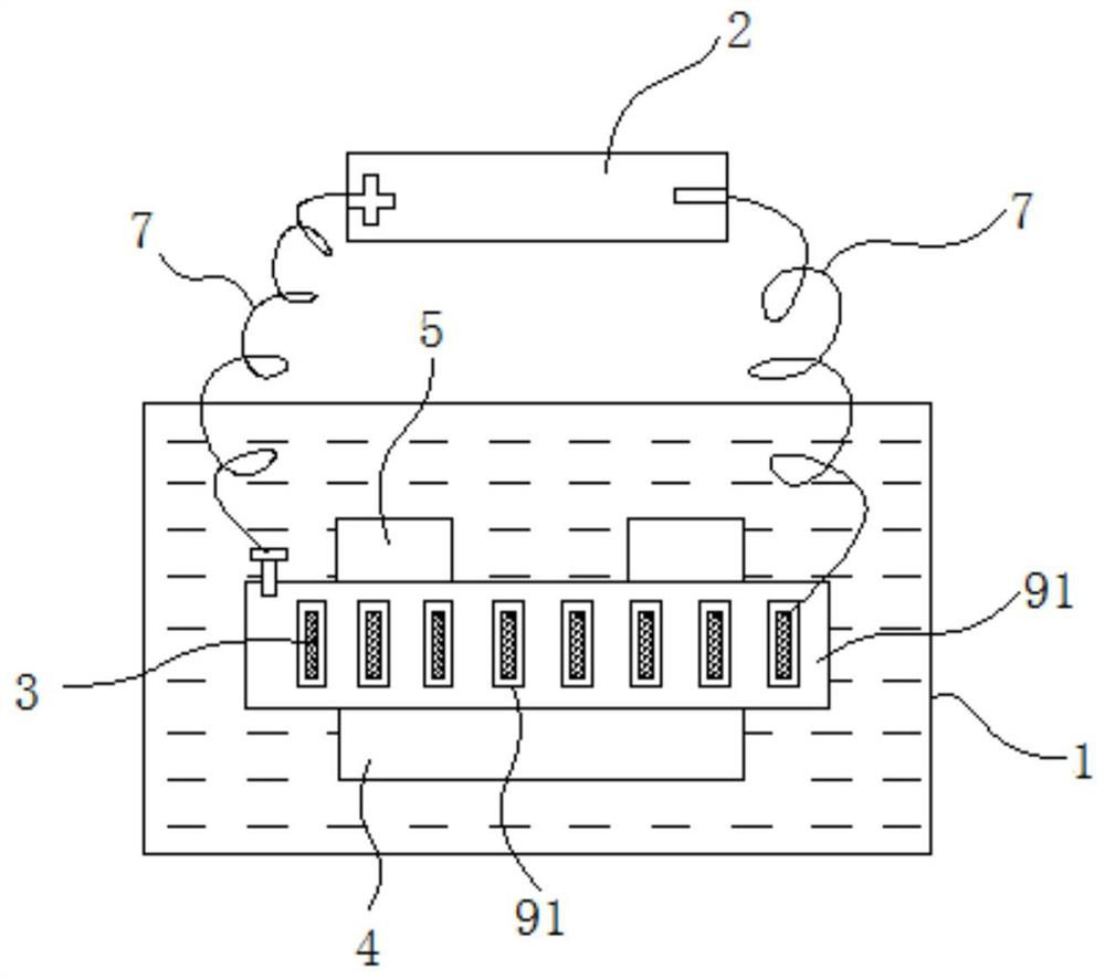
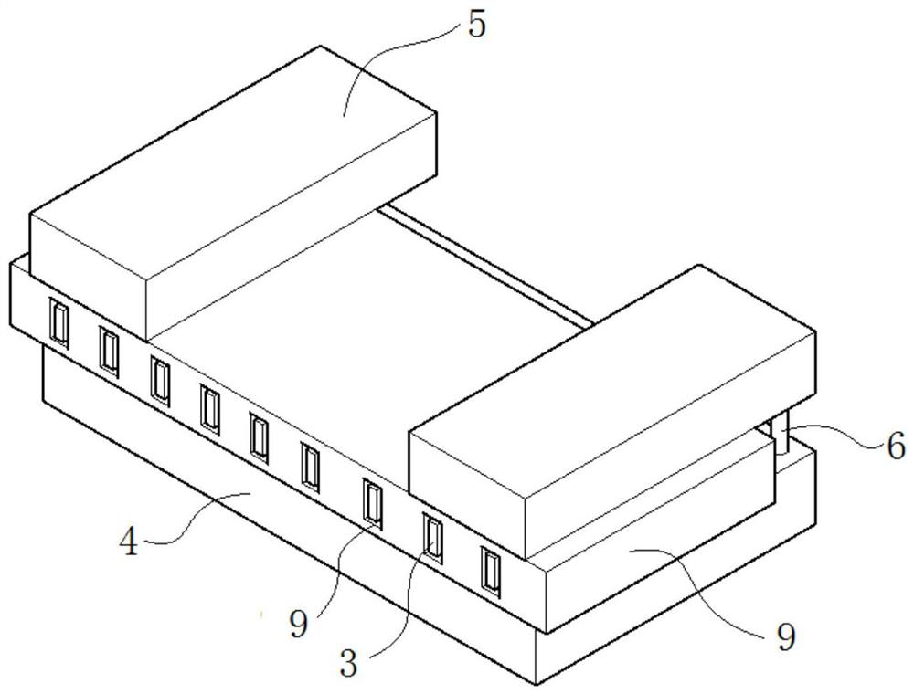
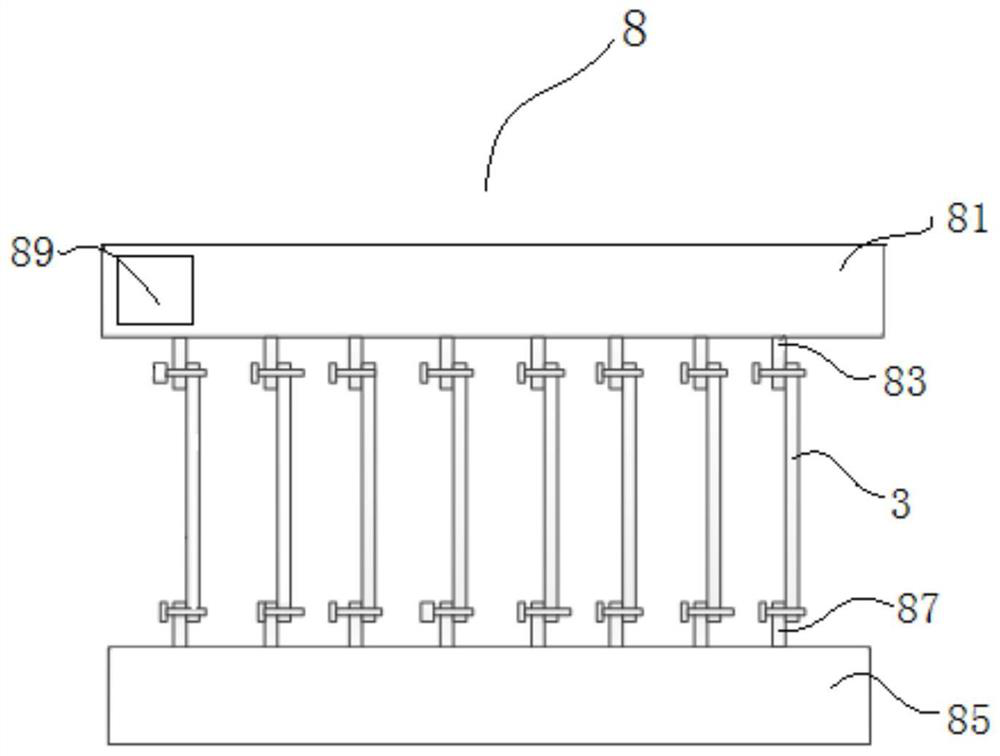
[0051] The micro-arc oxidation frock that the present invention adopts, as Figure 1-Figure 5 As shown, it includes an electrolytic cell 1 , a power supply 2 , an auxiliary cathode 3 , a bottom plate 4 , a fixing plate 5 and an auxiliary device 8 .

[0052] Such as figure 1 As shown, electrolytic solution is housed in the electrolytic cell 1, and the shape of the electrolytic cell 1 is set according to actual needs. The whole frock and the cold plate 9 are all submerged in the electrolyte, and the material of the cold plate 9 is aluminum alloy but not limited to aluminum alloy.

[0053] Such as figure 1 with figure 2 As shown, there is a space for pressing the cold plate 9 between the top wall of the bottom plate 4 and the bottom wall of the fixed plate 5, and for fixing the bottom plate 4 and the fixed plate 5, a fixed column 6 is provided between the bottom plate 4 and the fixed plate 5. In this implementation The fixing column 6 is a bolt or a screw in the example. Th...

Embodiment 2

[0066] An aluminum alloy cold plate part has 33 zigzag grooves with a length of 10 mm, a width of 5 mm and a depth of 200 mm, which is a typical large-area ultra-narrow gap micro-arc oxidation film preparation. It is difficult to prepare a uniform and stable oxide film layer by traditional micro-arc oxidation process . Adopt the micro-arc oxidation frock in embodiment 1 to carry out micro-arc oxidation, specifically comprise the following steps:

[0067] (1) cleaning

[0068] Using 3% aqueous solution of soda ash, the temperature is heated to 60 ° C, and then in HNO 3 (mass concentration 30%)+HF (mass concentration 5%) solution for brightening, and finally wash in hot water and dry in an oven for use. Carefully check whether there is water stain on the welding surface of the parts, if there is, be sure to clean it with alcohol or acetone.

[0069] (2) Partial protection

[0070] In non-MAO areas, spray paint stripper and cure at room temperature.

[0071] (3) Preparation ...

Embodiment 3

[0085] The difference between this embodiment and embodiment 2 is:

[0086] (1) The electrolyte includes sodium silicate 5g / L, sodium tungstate 5g / L, potassium hydroxide 1g / L, potassium fluoride 1g / L, and the rest is plasma water.

[0087] (2) The power supply parameters are as follows: The first stage: positive triangle wave. Voltage 320V, frequency 85HZ, oxidation time 1min; second stage: (a) positive pulse, voltage 410V, frequency 220HZ, oxidation time 20min, micro-arc oxidation solution temperature 18C; (b) negative pulse, voltage 126V, frequency 160HZ , oxidation time 15min, micro-arc oxidation solution temperature 20C.

[0088] Using the micro-arc oxidation tooling in Example 1, place the cold plate parts identical to those in Example 2 for micro-arc oxidation. After treatment, carry out an acidic salt spray test on the oxide film layer of the cold plate according to GJB1509A, 192h After visual inspection, the appearance is uniform, and there is no corrosion phenomenon...


PUM

PropertyMeasurementUnit
widthaaaaaaaaaa
thicknessaaaaaaaaaa
peel strengthaaaaaaaaaa

Abstract

The invention discloses a method for micro-arc oxidation in a cold plate air duct, and relates to the technical field of cold plate surface engineering. The method comprises the following steps of (1) cleaning and deoiling a cold plate, and then spraying strippable paint on a non-micro-arc oxidation area; (2) placing the cold plate on a micro-arc oxidation tool; and (3) adjusting power supply parameters and carrying out micro-arc oxidation. The method has the beneficial effects that by adopting the micro-arc oxidation tool, the shielding problem of an ultra-narrow gap power line is solved, the high uniformity of electric field distribution in an ultra-narrow gap is effectively ensured, the quality uniformity of a micro-arc oxidation film layer can be improved, and therefore it is ensured that the micro-arc oxidation quality of a product meets the application requirement. The micro-arc oxidation film layer prepared by the method has the capability of resisting acid salt mist for at least 192 hours, which is far better than the capability of resisting salt mist corrosion for 96 hours of a common micro-arc oxidation film layer.

Description

technical field [0001] The invention relates to the technical field of cold plate surface engineering, in particular to a method for micro-arc oxidation inside a cold plate air duct. Background technique [0002] At present, electronic equipment has been used for a long time in highly corrosive environments such as high temperature, high humidity, high salt, and many molds, and is facing serious material corrosion problems. As a key structural part, the cold plate is a key structural component, and the anti-corrosion problem of its key air-cooled protection area has become a One of the bottlenecks restricting the long-term high reliability of the product. Compared with the traditional anodic oxidation film, the micro-arc oxidation film has higher hardness, good corrosion resistance, wear resistance, thermal shock resistance and other properties, and has better environmental adaptability in harsh environments. application. For example, the patent disclosed micro-arc oxidati...

Claims


Application Information

Patent Timeline
Patent Type & Authority Applications(China)
IPC IPC(8): C25D11/04C25D11/16C25D11/18C25D7/00
CPCC25D11/04C25D11/16C25D11/18C25D7/00Y02P10/20
Inventor 方良超陈奇海王国超殷忠义侯江涛薛伟锋杨毅冯立王楠
Owner CHINA ELECTRONIC TECH GRP CORP NO 38 RES INST
Why Eureka
Try Eureka