
Camera lens base and camera module

A camera module and lens technology, which is applied in image communication, television, color television, etc., can solve the problems of manual trimming of the lens base, etc., and achieve the effect of eliminating the trimming process, beautiful appearance, and small deviation of external dimensions

Active Publication Date: 2015-04-08
TRULY OPTO ELECTRONICS
View PDF5 Cites 0 Cited by
  • Summary
  • Abstract
  • Description
  • Claims
  • Application Information

AI Technical Summary

Problems solved by technology

[0005] In view of this, the present invention provides a lens base and a camera module, which are used to solve the problem that the existing lens base needs manual trimming. The technical solution is as follows:

Method used


Image

  • Camera lens base and camera module
  • Camera lens base and camera module
  • Camera lens base and camera module

Examples


Embodiment Construction

[0022] In order to more clearly illustrate the technical solutions in the embodiments of the present invention or the prior art, the following will briefly introduce the drawings that need to be used in the description of the embodiments or the prior art. Obviously, the accompanying drawings in the following description are only It is an embodiment of the present invention, and those skilled in the art can also obtain other drawings according to the provided drawings without creative work.

[0023] In the description of the present invention, the orientations or positional relationships indicated by the terms "above", "bottom", "below" and the like are based on the orientations or positional relationships shown in the drawings, and are only for describing the present invention rather than requiring that the present invention must Constructed and operative in a particular orientation and therefore are not to be construed as limitations of the invention.

[0024] An embodiment o...


PUM


Abstract

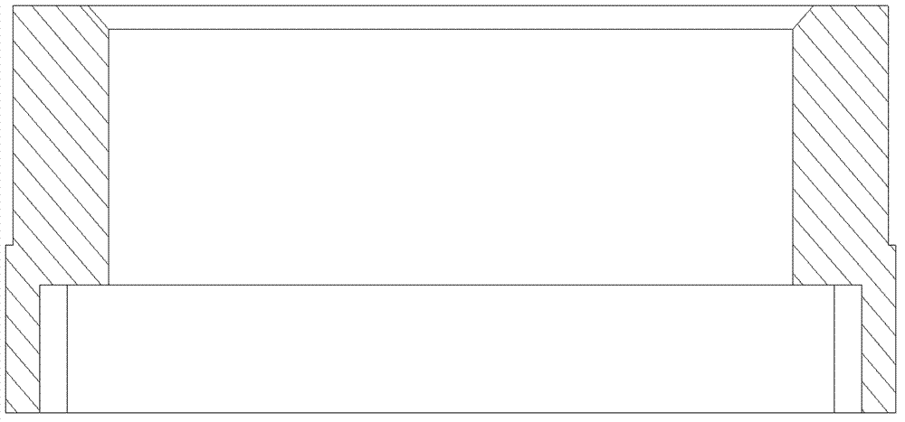
The invention provides a camera lens base which comprises a cylindrical barrel used for allowing a camera lens and a cavity to be installed in, wherein the cavity is connected with the cylindrical barrel and used for accommodating an imaging chip and a PCB ( printed circuit board) / FPC (flexible printed circuit) board, and the cavity comprises a first cavity and a second cavity; the surface of the inner wall of the second cavity in a vertical direction and the surface of the inner wall of the first cavity in a horizontal direction form steps; and the thickness of the wall of the camera lens base of the second cavity is smaller than that of the wall of the camera lens base of the first cavity. The invention further provides a camera module which comprises the camera lens base. According to the camera lens base and the camera module, when the steps on the inner wall of the camera lens base are overlapped on the PCB / FPC board, redundant carrying glue flows into a gap between the wall of the camera lens base below the steps and the PCB / FPC board, and the redundant glue is prevented from overflowing to other positions after the steps are carried, so that the trimming procedure is avoided; and simultaneously, trimming is not required, so that the deviation of the physical dimension of a product is small.

Description

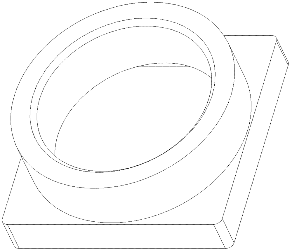
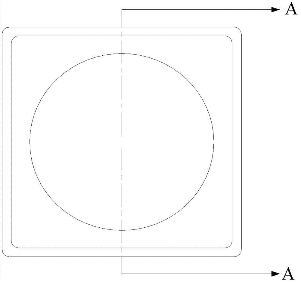
technical field [0001] The invention relates to the technical field of camera modules, in particular to a lens base and a camera module. Background technique [0002] The lens base is a mechanical component in the camera module, which is used to fix the lens on the imaging chip. By adjusting the relative position between the lens and the lens base, the imaging surface of the lens coincides with the imaging chip, that is, focusing. [0003] figure 1 It is a schematic diagram of the structure of a common lens base, figure 2 for figure 1 Bottom view of the base of the medium lens, image 3 for figure 2 The A-A direction sectional view of the middle lens base, in the camera module, figure 1 The lens base in the lens is fixed on the PCB / FPC (reinforced steel sheet) by carrying glue, such as Figure 4 As shown, the imaging chip 44 is contained in the cavity of the lens base 41 and is located above the PCB / FPC 43 . Usually, the bottom four sides of the lens base 41 are loca...

Claims


Application Information

Patent Timeline
Patent Type & Authority Patents(China)
IPC IPC(8): G02B7/02G03B17/12H04N5/225
Inventor 王军伟李建华
Owner TRULY OPTO ELECTRONICS
Learn More