
Three-dimensional image reduction method

A 3D image and image technology, applied in the field of image processing, can solve problems such as the lack of solutions to restore 3D images, and achieve the effect of improving subjective quality and improving objective quality

Active Publication Date: 2015-07-22
雷欧尼斯(北京)信息技术有限公司
View PDF3 Cites 0 Cited by
  • Summary
  • Abstract
  • Description
  • Claims
  • Application Information

AI Technical Summary

Problems solved by technology

[0010] However, there is no effective solution for restoring three-dimensional images in the prior art

Method used


Image

  • Three-dimensional image reduction method
  • Three-dimensional image reduction method
  • Three-dimensional image reduction method

Examples


Embodiment Construction

[0027] The present invention will be described in detail below in conjunction with the accompanying drawings and specific embodiments.

[0028] Herein, the present invention is described in detail by taking SideBySide as an example. For other 3D video formats, the difference is only in sampling, and there is no difference in the specific interpolation algorithm.

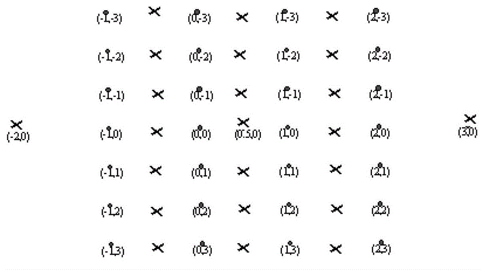
[0029] The present invention adopts a boundary-oriented interpolation algorithm, and its basic idea is to perform interpolation along the direction with the smallest gradient. In this method, gradients in three directions are selected for calculation, and more gradients can be selected for calculation. However, according to actual calculations, selecting more gradients has little effect on the change of interpolation results.

[0030] Let P(i,j) represent the value of the pixel whose coordinates are (i,j).

[0031] First, calculate the horizontal gradient G of the image according to the following formula 0 , 45 de...


PUM


Abstract

The invention discloses a three-dimensional image reduction method which comprises the following steps: calculating gradients in the directions of 0 degree, 45 degrees and 135 degrees according to formula (1), formula (2) and formula (3), wherein weighting coefficients are exhaustively chosen from 10 groups of coefficients according to PSNR (peak signal to noise ratio); and calculating interpolations in the directions of 0 degree, 45 degrees and 135 degrees by adopting the principle of interpolating in the direction with the smallest gradient, wherein formula (1), formula (2) and formula (3) refer to the patent specification. As the three-dimensional image reduction method adopts the principle of interpolating in the direction with the smallest gradient, image objective quality and particularly the subjective quality are improved.

Description

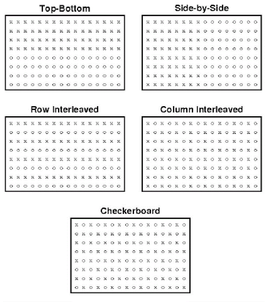
technical field [0001] The invention relates to the technical field of image processing, in particular to a three-dimensional image restoration method. Background technique [0002] Currently, a variety of 3D stereoscopic formats are coded in a frame-compatible mode. figure 1 Shown are several frame-compatible stereo coding formats, where x represents left view, and o represents right view. These modes first downsample the left view and right view in one mode to reduce the number of pixels to the original, then combine the left view and right view into one image, and then encode it into the code stream. For example, the side by side mode is to down-sample the left and right views horizontally, and then merge them into one image for encoding; while the top bottom mode down-samples both the left and right views vertically. Then merge them into one image for encoding. [0003] At the decoding end, since the left-view and right-view images of the recovered signal are both dow...

Claims


Application Information

Patent Timeline
Patent Type & Authority Patents(China)
IPC IPC(8): H04N13/00H04N21/40G06T3/40G06T5/00
Inventor 马士超
Owner 雷欧尼斯(北京)信息技术有限公司
Learn More