Device for the inductive transfer of electric energy

A technology of equipment and electric energy, applied in transmission systems, electric devices, electric energy management, etc., can solve problems involving costs and expenses

Inactive Publication Date: 2013-08-21
CONDUCTIX WAMPFLER
View PDF8 Cites 5 Cited by
  • Summary
  • Abstract
  • Description
  • Claims
  • Application Information

AI Technical Summary

Problems solved by technology

However, both solutions require specific communications technology hardware on the primary and secondary side, which involves corresponding costs

Method used


Image

  • Device for the inductive transfer of electric energy
  • Device for the inductive transfer of electric energy

Examples


no. 1 example

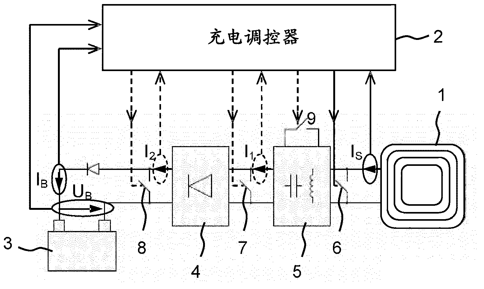
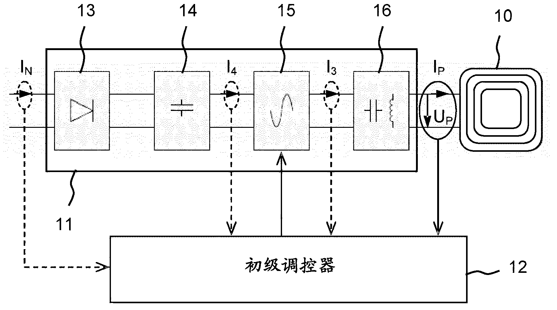
[0026] According to the first embodiment of the present invention, a calculation device included in the charging controller 2 is calculated by the charging current I B The measured value of and its current theoretical value I 0 Find the charging current I B The size of the required reduction, which is passed through the ratio I 0 / I B give. The charge regulator is turned on for a time T 0 relative to the total cycle time T P Periodically close and open the short-circuit switch 6 with a duty cycle corresponding to the ratio I 0 / I B . The time profile of the primary power measured by the primary controller 12 also has the same duty factor T 0 / T P , the time profile likewise alternates periodically between two values ​​as a result of the operation of the switch 6 .

[0027] A calculation device included in the primary regulator 12 is determined by the duty cycle T 0 / T P Calculated for the charge current I B with its theoretical value I 0 Necessary for matching, t...


PUM


Abstract

The invention relates to a device for the inductive transfer of electric energy from a stationary unit having a current supply device and a primary inductance which is connected thereto, to a vehicle that is adjacent to said unit and has a secondary inductance. The vehicle has a secondary control element for adjusting the secondary power taken from the secondary inductance and comprises a control device, said control device enabling the withdrawn secondary power to be modified in steps. Said stationary unit comprises a primary control element for adjusting the primary power which can be injected into the primary inductance, which contains a first measuring device, said measuring device enabling an operational parameter, influenced by the secondary power, of the current supply device to be measured. The primary control element adjusts the primary power which can be injected in accordance with modifications of the operational parameter measured by the first measuring device. The secondary power can be switched preferably between two steps by the switching device and has in one of the steps, a value which is at least approximately zero.

Description

technical field [0001] The invention relates to a device for the inductive transmission of electrical energy according to the preamble of claim 1 . Background technique [0002] When charging the battery of an electric vehicle, it is necessary to adjust the charging current to an appropriate value at any time according to the specification of the battery and according to its current state of charge / state of charge. The charging electronics necessary for this can optionally be provided on the vehicle or in the charging station. In the inductive energy transfer from the charging station to the vehicle, the charging station must continuously provide the maximum possible charging power with the entire charging electronics arranged in the vehicle and this power must then be reduced in the vehicle to the currently required value. This leads to relatively high power losses both on the primary side and on the secondary side and requires a correspondingly robust and therefore expen...

Claims


Application Information

Patent Timeline
Patent Type & Authority Applications(China)
IPC IPC(8): B60L11/18H02J7/02
CPCY02T90/14B60L3/04B60L2210/30B60L2210/40B60L2240/547B60L2240/549Y02T10/7072Y04S30/14B60L53/65H04B5/0037B60L53/53B60L53/305B60L53/122B60L58/00H02J7/00034H02J7/342H02J7/345Y02T10/72Y02T90/12Y02T90/167Y02T90/16Y02T10/70H02J50/80H02J50/12B60L3/0046B60L53/12
Inventor P·阿瑟林
Owner CONDUCTIX WAMPFLER
Why Eureka
Try Eureka