A photo processing method with a rotatable viewfinder frame

A processing method and framing technology, which are applied in image data processing, graphic image conversion, instruments, etc., and can solve problems such as skew, inability to rotate, and rectangular finder frames that can only move.

Inactive Publication Date: 2015-09-23
SOUTHWEST UNIV
View PDF3 Cites 2 Cited by
  • Summary
  • Abstract
  • Description
  • Claims
  • Application Information

AI Technical Summary

Problems solved by technology

[0003] In the specific photo operation, often due to the uncertainty of the subject (for example: the same height, short, fat and thin, or even some shoulders or heads are skewed), this requires the operator to manually adjust the camera through the tripod handle (among them: upper, Down, left, right, and adjustment are a little more convenient, but it is more troublesome to rotate the camera)
When taking a large number of pictures, it is necessary to constantly adjust the camera, and repeatedly remind the subject to tilt his head to the left (right), and they are sitting opposite the operator, and often cannot correctly understand the indicated direction, especially when there is someone When a large number of people line up to take pictures, repeated reminders often make the mouth dry and seriously affect the speed of taking pictures
In the final photo effect, a large part of the head of the photo is often not straight, which affects the visual effect to a certain extent
[0004] Although this type of software is relatively easy to develop, it has two disadvantages: First, when moving the viewfinder, it needs to copy the original viewfinder image in real time and redraw it at the same position in the top-level visible area, which takes up a lot of memory and CPU, and is prone to Smear; Second, the rectangular viewfinder can only be moved but cannot be rotated, and the tilt correction of the camera can only be performed through the tripod handle

Method used


Image

  • A photo processing method with a rotatable viewfinder frame
  • A photo processing method with a rotatable viewfinder frame
  • A photo processing method with a rotatable viewfinder frame

Examples


Embodiment Construction

[0040] The present invention will be further described below in conjunction with specific embodiments and accompanying drawings.

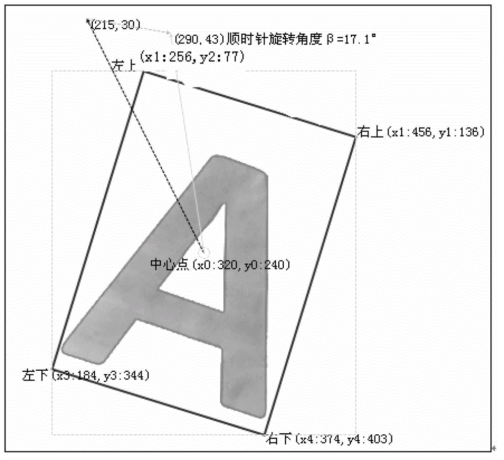
[0041] Such as figure 1 As shown, known parameters: frame width W=200, height H=280.

[0042] (1) Calculate the viewfinder frame rotation angle: β, the case data is as follows:

[0043] a. Get the coordinates of the center of the viewfinder frame (x 0 ,y 0 ) is (320,240);

[0044] b. Get the mouse coordinates of the starting point of rotation (x _old ,y _old ) is (215,30);

[0045] c. Get the mouse coordinates of the end point of the rotation (x _new ,y _new ) is (290,43);

[0046] d. Calculate the rotation angle β, and the public calculation is as follows:

[0047] β = a tan ( y 0 - y _ new ...


PUM


Abstract

The invention discloses a method for shooting by rotating a viewing frame. The method comprises a step of acquiring a center coordinate of the viewing frame, a step of rotating a picture, a step of calculating a rotating angle beta, a step of calculating the polar coordinate system angles of four corners of the viewing frame which is rotated by the angle beta, a step of calculating the relative coordinates of a Descartes rectangular coordinate system of the four corners of the rotated viewing frame, a step of calculating the absolute coordinates of the four corners of the rotated viewing frame, a step of drawing a rectangular viewing frame, a step of calculating the minimum enclosing rectangle of the rotated viewing frame, a step of tailoring an image in the minimum enclosing rectangle for the first time, a step of rotating the image reversely by an angle of beta with the viewing frame as the center, and a step of tailoring the image for the second time with the center of the view frame as the center, with W as the width and with H as the height. According to the method, the viewing frame within a video area can be moved and rotated, the head or the body of a shooting target can be corrected in a dynamically tilting mode, and the purposes that the shooting area is accurately defined and the shooting process is accelerated are achieved.

Description

technical field [0001] The invention relates to an auxiliary rib method of a previewable electronic photographing system with a rotatable viewing frame. Background technique [0002] At present, the technology of taking pictures of portraits by computer is mature and widely used. The camera software on the market is limited to adding a movable rectangular viewfinder frame on the background video in terms of development technology. When the mouse enters this area to move, it will redraw by copying the image of the rectangular frame area in real time, such as figure 1 shown. [0003] In the specific photo operation, often due to the uncertainty of the subject (for example: the same height, short, fat and thin, or even some shoulders or heads are skewed), this requires the operator to manually adjust the camera through the tripod handle (among them: upper, Down, left, right, and adjustment are a little more convenient, but it is more troublesome to rotate the camera). When t...

Claims


Application Information

Patent Timeline
Patent Type & Authority Patents(China)
IPC IPC(8): G06T3/60
Inventor 周素梅邓蜀国
Owner SOUTHWEST UNIV
Why Eureka
Try Eureka