
Plant greenhouse and stepless light-adjusting method thereof

A technology for greenhouses and plants, applied in the field of greenhouses for plants, can solve the problems of limited accommodation space of greenhouses, affecting yield, inconvenient humidity control, etc.

Active Publication Date: 2013-09-04
盐城鹏里医疗科技有限公司
View PDF6 Cites 1 Cited by
  • Summary
  • Abstract
  • Description
  • Claims
  • Application Information

AI Technical Summary

Problems solved by technology

[0005] The wet curtain is the main equipment for adjusting the humidity in the greenhouse. In order to keep the existing wet curtain moist, a pump must be used to fill and humidify the wet curtain after a certain time interval. The water transported by the pump flows down from the top of the wet curtain to make the whole The wet curtain is soaked, but this method has the following two disadvantages: 1. The pump needs to run at intervals, and the power consumption is relatively large; 2. The humidity of the wet curtain is uneven after water injection, and the humidity is high during water injection. After a period of time, the humidity is low, which brings inconvenience to the humidity control in the greenhouse. During the period of low humidity, it may be necessary to turn on the humidifier to increase the humidity, which causes additional power consumption
[0007] The existing seedbeds are usually fixed. In order to facilitate maintenance, aisles are set between the seedbeds. Although such a structure is easy to operate, it has the following disadvantages: the accommodation space of the greenhouse is limited, and the seedbeds and aisles occupy a large area. space, which will inevitably reduce the amount of planting in greenhouses, thereby affecting the yield

Method used


Image

  • Plant greenhouse and stepless light-adjusting method thereof
  • Plant greenhouse and stepless light-adjusting method thereof
  • Plant greenhouse and stepless light-adjusting method thereof

Examples


Embodiment 1

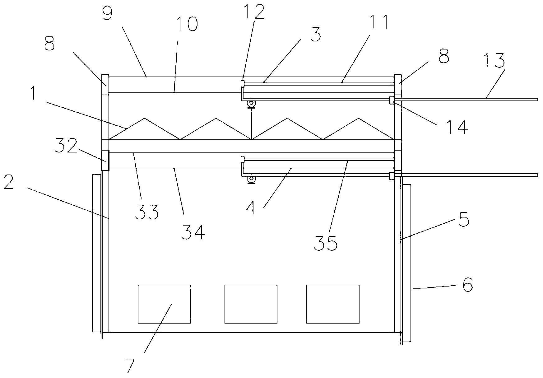
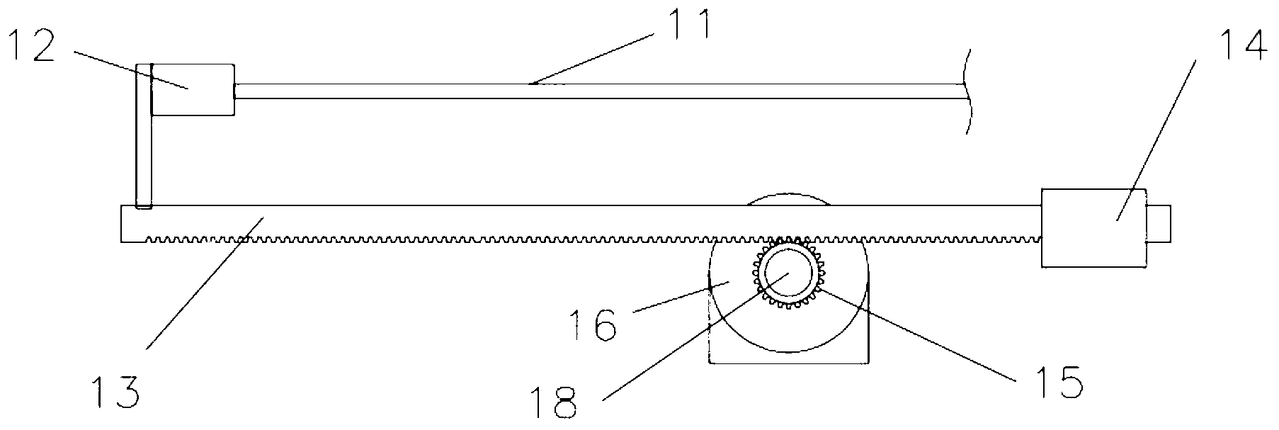
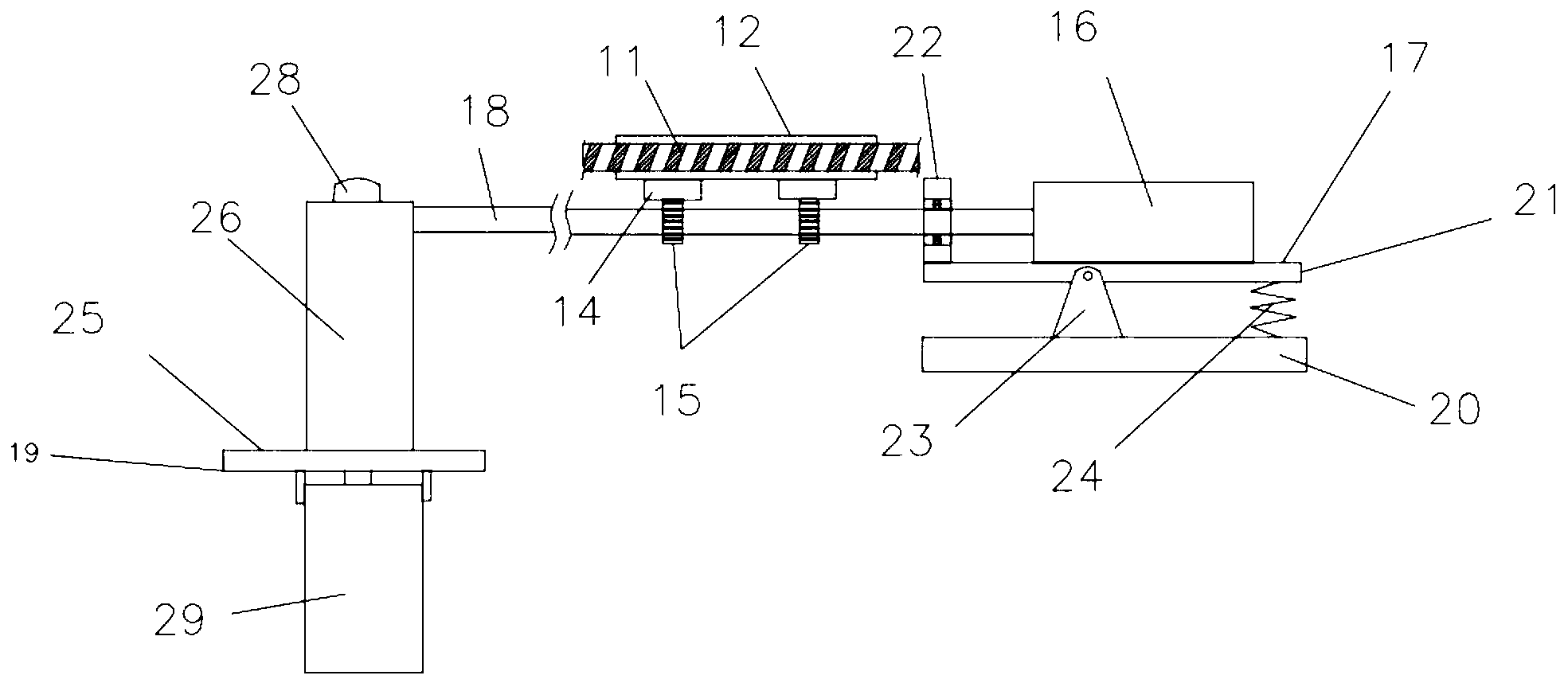
[0093] like figure 1 As shown, the plant greenhouse described in this embodiment mainly includes a greenhouse roof, a greenhouse side wall, an external net device, an inner net device, a wet curtain, a side window and a seedbed. Above, the outer net device is arranged above the warm shed roof, the inner net device is arranged under the warm shed roof, the top of the wet curtain is fixed on the side wall of the warm shed, the side window is arranged on the outside of the wet curtain, and the seedbed is arranged under the warm shed roof. ,like figure 2 , 3 It is characterized in that: the outer net device is mainly composed of an upper pulling net beam, an upper laminating line, an upper supporting film line, an outer net, an upper driving net block, an upper rack rod with a rack on the bottom, and an upper rack rod. It is composed of seat, upper gear, external grid motor, upper motor seat, upper rotating shaft and upper rotating shaft seat;

[0094] Among them, the upper dr...

Embodiment 2

[0111] like Figure 7 , 8 As shown in the figure, the plant greenhouse described in this embodiment is different from Embodiment 1 in that the inner mesh device is mainly composed of a lower mesh beam, a lower pressure film line, a lower support film line, an inner mesh, a lower drive mesh block, It consists of net rolling rod, net rolling bearing, servo net rolling motor, lower rack rod with rack on the bottom, lower rack rod seat, lower gear, inner net motor, lower rotating shaft and lower rotating shaft seat;

[0112] Wherein, the lower drive mesh block, the lower rack rod, and the lower rack rod seat are made of aluminum alloy; the aluminum alloy has the advantages of firmness, lightness and corrosion resistance; (as a variation of this embodiment, the lower drive mesh block, the lower rack The rod, lower rack rod seat can also be replaced by stainless steel or copper or hard plastic ;)

[0113] There are two pull-down mesh beams and they are located on both sides under ...

Embodiment 3

[0123] like Figure 9As shown in the figure, the plant greenhouse described in this embodiment is different from the second embodiment in that the upper and lower driving mesh blocks have the same structure as the driving mesh block body, and in the longitudinal section, the driving mesh block The upper part of the body is provided with a first narrow slot with an upward opening, the lower part is provided with a second narrow slot with a downward opening, its side is provided with a third narrow slot with an opening to the side, and the other side is provided with a connection mesh. A flared groove with a large inside and a small outside, wherein the narrow groove is a groove structure with a large internal space and a small notch;

[0124] The first narrow slot is provided with a bolt and a gasket, the threaded section of the bolt protrudes from the slot of the first narrow slot, and the gasket restricts the bolt head in the first narrow slot; the gasket There is a rubber b...


PUM


Abstract

The invention discloses a plant greenhouse which mainly comprises a greenhouse roof, greenhouse side walls, an outer net device, an inner net device, wet curtains, side windows and seedbeds. The greenhouse roof is arranged above the greenhouse side walls, the outer net device is arranged above the greenhouse roof, the inner net device is arranged below the greenhouse roof, the tops of the wet curtains are fixed on the greenhouse side walls, the side windows are arranged on the outer sides of the wet curtains, the seedbeds are arranged below the greenhouse roof, inclined through holes are densely distributed on an outer net, a vertical plane identical with the inclining direction of the inclined through holes is parallel to a vertical plane where an upper rotating shaft is positioned, and fixed supporting legs are arranged on the lower portion of each seedbed frame. The plant greenhouse has the advantages that the whole outer net can realize one inclining action, the inclined through holes are densely distributed on the outer net, and light-transmitting areas of the inclined through holes change along inclining of the outer net, so that light-transmitting effect of the outer net can be adjusted, stepless light adjusting is realized, and light-adjusting effect is better.

Description

[0001] This patent application is a divisional application for an invention patent application (the application number is 2011101945461, the application date is 2011-7-11, and the name is plant greenhouse) technical field [0002] The invention relates to agricultural equipment, in particular to a greenhouse for plants. Background technique [0003] With the development of society and the improvement of automation, plant factories are more and more widely used in agriculture. Plant factories usually mainly include closed spaces such as greenhouses, and plants are set in the greenhouses. When in use, the artificial simulation of climate is realized by automatic adjustment of temperature, humidity, light, etc., so as to provide a suitable production environment for plants. [0004] The existing greenhouse mainly includes the top of the greenhouse, the side walls of the greenhouse, the outer net device, the inner mesh device, the wet curtain, the side window and the seedbed. A...

Claims


Application Information

Patent Timeline
Patent Type & Authority Applications(China)
IPC IPC(8): A01G9/14A01G9/10A01G9/22
CPCY02A40/25
Inventor 来宝根
Owner 盐城鹏里医疗科技有限公司
Learn More