Glass wiping device

A glass wiper and shell technology, applied in cleaning equipment, home appliances, applications, etc., can solve the problems of long cleaning cycle, high risk, difficult to scrub, etc., to achieve simple structure, good safety, and reduce the risk of falling. Effect

Inactive Publication Date: 2013-09-04
WUJIANG DONGXIN PLASTIC PACKAGING PLANT
View PDF5 Cites 1 Cited by
  • Summary
  • Abstract
  • Description
  • Claims
  • Application Information

AI Technical Summary

Problems solved by technology

[0002] When cleaning windows, especially the window glass of high-rise buildings in many cases, it is difficult to scrub, unless a large-scale cleaning is performed from the outside, but this method is costly, dangerous, and the cleaning cycle is also very long

Method used


Image

  • Glass wiping device
  • Glass wiping device
  • Glass wiping device

Examples


Embodiment Construction

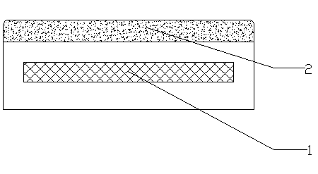
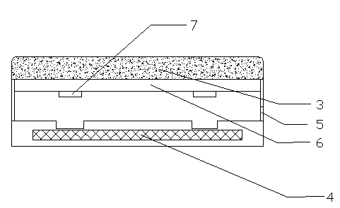
[0022] Such as Figure 1~4 As shown, a glass wiper includes a connecting rod, a wiper A and a wiper B;

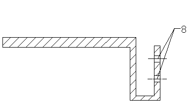
[0023] A connecting plate is arranged on the connecting rod, and a mounting hole 8 is arranged on the connecting block;

[0024] The wiping plate A includes a cleaning head A1, a housing and a magnet block A2, the magnet block A2 is arranged inside the housing A, and the cleaning head A2 is arranged outside the housing A; the wiping board B includes a cleaning head B3, a housing B , iron plate and magnet block B4, the inside of the housing B is provided with a cavity, the iron plate moves in the cavity facing or facing away from the cleaning head B3, and the magnet block is placed outside the cavity away from the cleaning head B3 side; wherein the magnetic force of the magnet block B4 in the wiper B is less than the magnetic force of the magnet block A1 in the wiper A; the wiper B is also provided with an opening 5, and the connecting rod passes through the opening 5 throu...


PUM


Abstract

The invention discloses a glass wiping device. Two brush heads are oppositely arranged, and a magnet is arranged between the brush heads to achieve double-surface wiping of glass, wherein a clamping mechanism is arranged in one brush head. The glass wiping device can be conveniently recovered through a connecting rod after the glass is wiped. The glass wiping device has the advantages of being perfect in safety, simple in structure and the like.

Description

technical field [0001] The invention relates to a glass cleaning tool, in particular to a glass wiper. Background technique [0002] When cleaning windows, especially the window glass of high-rise buildings in many cases, it is difficult to scrub unless large-scale cleaning is carried out from the outside, but this method is costly, dangerous, and the cleaning cycle is also very long. Contents of the invention [0003] The invention provides a glass wiper which can easily wipe glass windows. [0004] The present invention is achieved in the following manner: [0005] A glass wiper, the glass wiper includes a connecting rod, a wiper A and a wiper B; [0006] The connecting rod includes a connecting plate, and the connecting plate is provided with mounting holes; [0007] The wiper A includes a cleaning head A, a casing A and a magnet block A, the magnet block A is arranged inside the casing A, and the cleaning head A is arranged outside the casing A; [0008] The wiping...

Claims


Application Information

Patent Timeline
IPC IPC(8): A47L1/12
Inventor 董建中
Owner WUJIANG DONGXIN PLASTIC PACKAGING PLANT
Why Eureka
Try Eureka