Cleaning device

A technology for cleaning equipment and cleaning heads, applied in cleaning methods and utensils, cleaning methods using tools, chemical instruments and methods, etc., can solve the problems of long cleaning time, low work efficiency, etc. The effect of improving cleaning efficiency

Inactive Publication Date: 2013-09-04
潘燕 +2
View PDF6 Cites 7 Cited by
  • Summary
  • Abstract
  • Description
  • Claims
  • Application Information

AI Technical Summary

Problems solved by technology

For some elderly people, activities such as wiping the floor or walls that require bending and climbing are even more dangerous.
For some stubborn stains, it often takes more effort to scrub repeatedly, which brings a lot of inconvenience to life, and the cleaning time is longer and the work efficiency is low.

Method used


Image

  • Cleaning device
  • Cleaning device

Examples


Embodiment 1

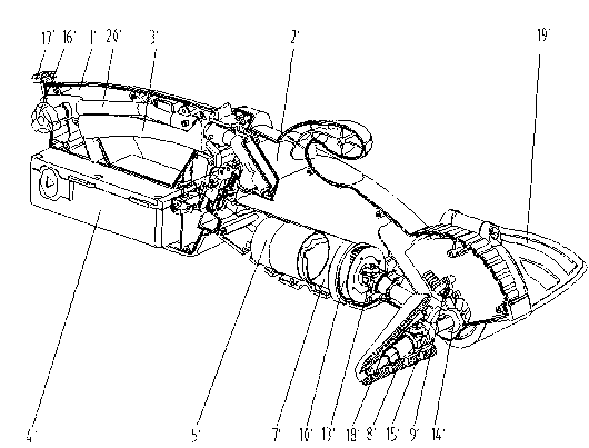
[0022] Example 1, see figure 1 , a cleaning device, comprising: a head assembly and a handle assembly, the handle assembly includes a handle casing 1', the head assembly includes a head casing 2', the handle casing 1' and the head casing 2' pass through The bayonet is connected with the machine head, the handle housing 1' and the machine head housing 2' can be connected in combination, and can also be an inseparable integrated component. The handle housing 1' is provided with a switch assembly 3' and The power supply 4' and the switch assembly 3' are composed of electric control switches and liquid valves. After the switch assembly 3' is turned on, the water source and electric energy enter the machine head assembly through the corresponding sockets. The switch assembly 3' is connected to the power supply 4', and the machine head The casing 2' is equipped with a power source 5', a reduction box 7' and a water pump assembly 6', the power source 5' is connected to the reduction ...

Embodiment 2

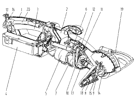
[0027] Example 2, see figure 2 , a cleaning device, comprising: a head assembly and a handle assembly, the handle assembly includes a handle casing 1, the head assembly includes a head casing 2, the handle casing 1 and the head casing 2 are connected by a bayonet and a machine The handle casing 1 and the machine head casing 2 can be connected in combination, or can be an inseparable integrated component. The handle casing 1 is provided with a switch assembly 3 and a power supply 4, and the switch assembly 3 is controlled by the controller. Composed of an electric switch and a liquid valve, after the switch assembly 3 is turned on, the water source and electric energy enter the machine head assembly through the corresponding socket, the switch assembly 3 is connected to the power supply 4, and the machine head casing 2 is provided with a power source 5 and a reduction box 7 It is connected with the water pump assembly 6, the power source 5 and the reduction box 6, the power so...


PUM


Abstract

The invention discloses a cleaning device which comprises a machine head assembly and a handle assembly. The handle assembly comprises a handle machine shell. The machine shell assembly comprises a machine head machine shell, and the handle machine shell and the machine head machine shell are connected in a matched mode. A switch assembly is arranged in the handle machine shell, and a driving portion and a cleaning portion are arranged in a machine head shell body. The driving portion and the cleaning portion are connected in a matched mode. The driving portion comprises a power source and a reduction box, wherein the reduction box is arranged on the power source in a matched mode. The switch assembly controls the power source and a water source switch. The cleaning device further comprises a water pump arranged in the machine head machine shell. The water pump and the reduction box are connected through a transmission assembly. By means of the method, the cleaning device can reduce time in cleaning and improve cleaning efficiency, and is simple in operation and capable of automatically providing a hairbrush with water.

Description

technical field [0001] The invention relates to the field of cleaning devices, in particular to a cleaning device. Background technique [0002] As we all know, with the progress and development of science, machinery has gradually replaced human labor, especially for some jobs that are highly repetitive, physically exhausting, and easy to feel tired. In daily life, when people clean objects, they often need to repeatedly scrub with a rag, especially for special objects such as cars, floors, and walls. Due to their special location and size, they consume a lot of energy during cleaning, and often feel backache. pain. For some elderly people, activities such as wiping the floor or walls that require bending over and climbing are even more dangerous. For some stubborn stains, it often takes more effort to scrub repeatedly, which brings a lot of inconvenience to life, and the cleaning time is longer and the work efficiency is low. Contents of the invention [0003] The tech...

Claims


Application Information

Patent Timeline
Patent Type & Authority Applications(China)
IPC IPC(8): B08B1/04B08B13/00
Inventor 潘燕包荣辉王丽云
Owner 潘燕
Why Eureka
Try Eureka