Round steel rolling feeding equipment

A technology for feeding equipment and round steel, applied in the field of mechanical processing, can solve the problems of unbalanced round steel, inconvenient and inaccurate feeding of round steel, etc., and achieve the effect of easy positioning, easy identification, and convenient transportation.

Inactive Publication Date: 2013-09-04
四川东方能源科技股份有限公司
View PDF5 Cites 1 Cited by
  • Summary
  • Abstract
  • Description
  • Claims
  • Application Information

AI Technical Summary

Problems solved by technology

[0004] The purpose of the present invention is to overcome the shortcomings of the prior art that the round steel is easy to lose balance, and the feeding of the round steel is inconvenient and inaccurate, and provides a rolling feeding equipment for the round steel

Method used


Image

  • Round steel rolling feeding equipment
  • Round steel rolling feeding equipment
  • Round steel rolling feeding equipment

Examples


Embodiment 1

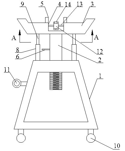
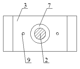
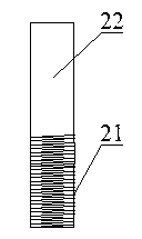
[0033] Such as Figure 1~Figure 3 As shown, the round steel rolling feeding equipment includes a bracket 1, a lifting rod 2, a supporting platform 3, a runner 12 and a rotating shaft 13, the top of the bracket 1 is provided with a threaded hole, the lower part of the lifting rod 2 is a threaded section 21, and the lifting rod 2 The upper part of the cylindrical section 22, the threaded section 21 is threadedly matched with the threaded hole, the cylindrical end 22 is connected with the bottom of the support platform 3, the support platform 3 is provided with a groove 4, and the runner 12 is fixed in the groove 4 through the rotation of the rotating shaft 13 .

[0034] In this embodiment, when in use, the middle part of the round steel is placed on the support platform 3, and then the up and down movement of the round steel is realized by rotating the elevating rod 2. Since the up and down movement of the round steel is realized through thread fit, the whole process is very st...


PUM


Abstract

The invention discloses round steel rolling feeding equipment which comprises a support, a lifting rod, a bearing platform, a rotary wheel and a rotary shaft. A threaded hole is formed in the top of the support, the lower portion of the lifting rod is a threaded section, the upper portion of the lifting rod is a cylindrical section, the threaded section and the threaded hole are in screw-thread fit, the cylindrical section is connected with the bottom of the bearing platform, a groove is formed in the bearing platform, and the rotary wheel is rotatably fixed in the groove through the rotary shaft. The round steel rolling feeding equipment has the advantages that up-down moving of round steel can be realized by rotating the lifting rod, the whole process is quite stable, and no vibration is caused, so that the problem of falling of the round steel due to balance loss is solved; the rotary wheel is arranged, and the round steel is arranged on the rotary wheel, so that feeding of the round steel can be realized conveniently and quickly only by pushing the round steel, and cutting positions of the round steel are easy to find.

Description

technical field [0001] The invention relates to the field of mechanical processing, in particular to a round steel rolling feeding equipment. Background technique [0002] When cutting round steel, it is necessary to lift the round steel to a height suitable for the cutting machine. At present, the height of the round steel is mainly raised by means of crane hoisting. The hook of the crane is connected with the load-bearing steel chain or lifting belt, and then the middle part of the round steel is connected through the steel chain or lifting belt, so as to lift the round steel. The vibration of the steel chain or lifting belt is very easy to cause the round steel to lose its balance and fall. During the whole process, manpower is required to control the balance of the round steel, which poses a huge safety hazard. Once the round steel falls, it is very easy to cause the staff to be injured. [0003] On the other hand, after cutting off a section of round steel, it is nec...

Claims


Application Information

Patent Timeline
Patent Type & Authority Applications(China)
IPC IPC(8): B23Q7/00
Inventor 王曾勇叶礼
Owner 四川东方能源科技股份有限公司
Why Eureka
Try Eureka