Detachable vehicle-mounted computer support
A vehicle-mounted computer, disassembly and connection technology, applied in the field of machinery, can solve the problems of reducing the overall aesthetics of car interiors, not being suitable for different vehicles, unfavorable distribution of other components, etc., achieving the effects of simple structure, convenient operation, and reduced development costs
- Summary
- Abstract
- Description
- Claims
- Application Information
AI Technical Summary
Problems solved by technology
Method used
Image
Examples
Embodiment 1
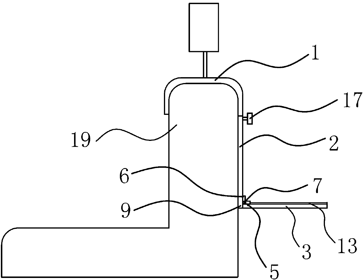
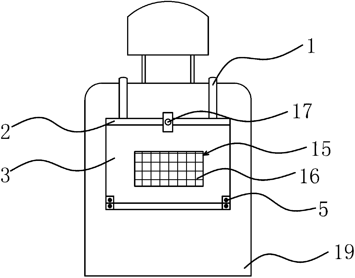
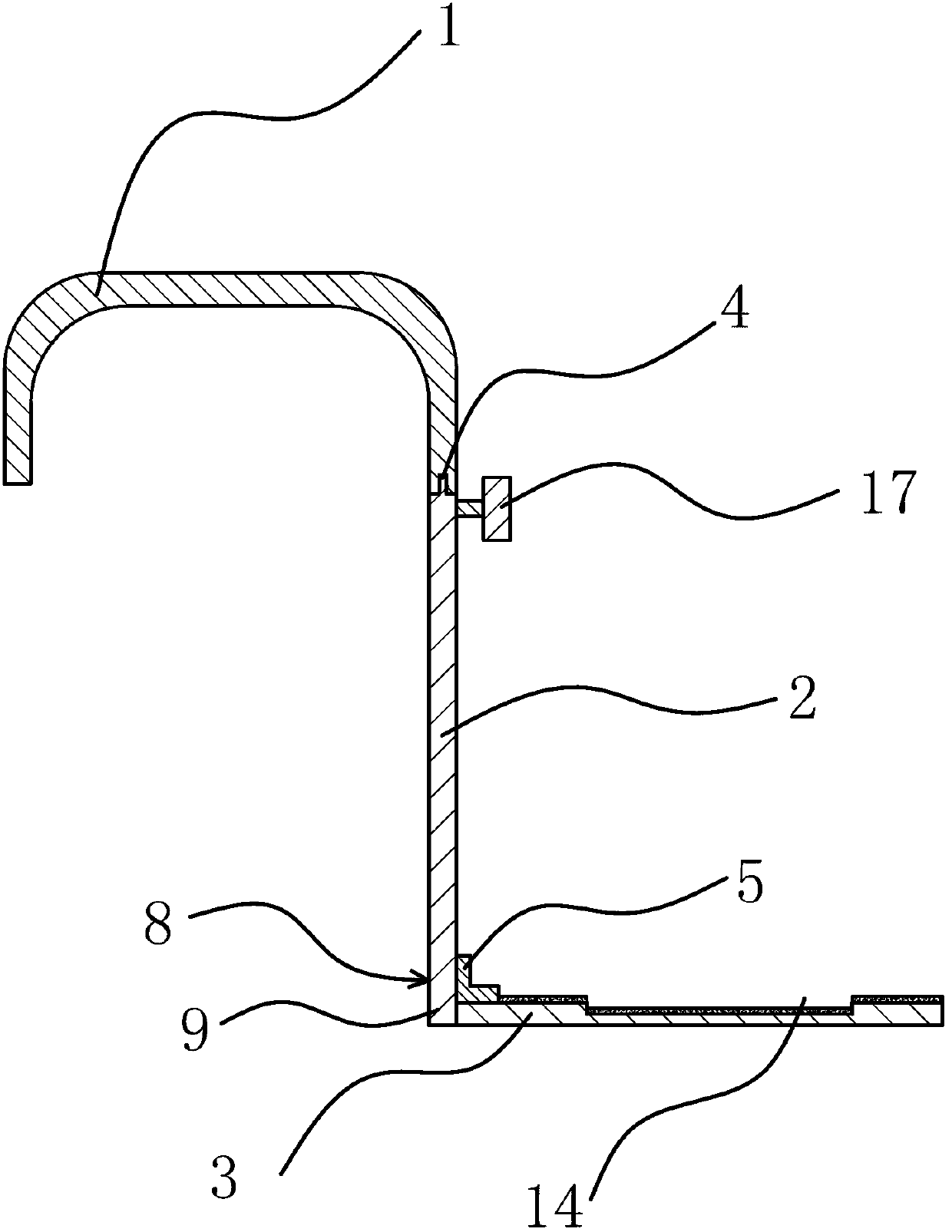
[0032] Such as figure 1 , figure 2 , image 3As shown, the computer bracket includes a hook 1, a baffle 2 and a support plate 3, wherein the support plate 3 is made of ABS plastic or medium density fiberboard, and the hook 1 is elastic, and the opening of the hook 1 faces the side of the baffle 2 The lower end, the head and the tail of the hook 1 can be clamped on the front and rear sides of the backrest 19 from the top of the backrest 19 of the car seat. The upper end of the hook 1 and the baffle 2 is detachably connected. In this embodiment, the upper end of the baffle 2 has a buckle 4 , the hook 1 has a slot, and the buckle 4 can be snapped into the slot. As another solution, several mounting holes that run through the surface of the baffle plate 2 can also be provided on the upper end of the baffle plate 2, and several threaded holes corresponding to the mounting holes one by one are provided on the hook 1, and the threaded holes and the corresponding Corresponding mou...
Embodiment 2
[0037] Such as Figure 4 As shown, this embodiment is roughly the same as Embodiment 1, the difference is that the locking structure 8 in this embodiment includes two slide rails that are fixedly connected to the lower end of the baffle plate 2, and the length direction of the slide rails is in line with that of the baffle plate 2. are perpendicular to each other, and a supporting plate 18 is slidably connected to the slide rail, and the supporting plate 18 is located below the hinge point of the baffle plate 2 and the supporting plate 3 . After the support plate 18 is designed, when the baffle plate 2 is turned over to the preset position, the baffle plate 2 can abut against the support plate 18, so that the baffle plate 2 and the support plate 3 are fixed to each other, and the length of the support plate 3 can be Adjust the position of the supporting plate 18 to better support the support plate 3 .
Embodiment 3
[0039] Such as Figure 5 As shown, this embodiment is roughly the same as Embodiment 1, the difference is that the locking structure 8 in this embodiment includes several protrusions 10 fixed on the side of the baffle plate 2, and fixed on the side of the support plate 3. There are several protrusions 11 corresponding to the protrusions 10, and the locking structure 8 also includes several connecting ropes 12, and the two ends of the connecting ropes 12 are respectively tied to the protrusions 10 and the protrusions corresponding to the protrusions 10. Raised two 11 on. In addition, the locking structure 8 can also include several bolt holes 1 on the side of the baffle plate 2, and several bolt holes 2 corresponding to the bolt holes 1 are provided on the side of the support plate 3, and the locking structure 8 also includes It includes a number of connecting rods, and the two ends of the connecting rod are respectively provided with a through hole 1 and a through hole 2, and...
PUM
 Abstract
Description
Claims
Application Information
 - R&D
- Intellectual Property
- Life Sciences
- Materials
- Tech Scout
- Unparalleled Data Quality
- Higher Quality Content
- 60% Fewer Hallucinations
Browse by: Latest US Patents, China's latest patents, Technical Efficacy Thesaurus, Application Domain, Technology Topic, Popular Technical Reports.
© 2025 PatSnap. All rights reserved.Legal|Privacy policy|Modern Slavery Act Transparency Statement|Sitemap|About US| Contact US: help@patsnap.com


