Electric anti-theft directional lock

A direction lock and electric technology, applied in the field of locks, can solve the problems of poor anti-theft effect and achieve the effect of increasing the security barrier

Active Publication Date: 2013-09-04
SHENZHEN TAILG ELECTRIC VEHICLE
View PDF7 Cites 11 Cited by
  • Summary
  • Abstract
  • Description
  • Claims
  • Application Information

AI Technical Summary

Problems solved by technology

[0003] The technical problem to be solved by the present invention is to provide an electric anti-theft direction lock with better anti-theft effect in view of the defect that the above-mentioned traditional direction lock of the prior art has poor anti-theft effect.

Method used


Image

  • Electric anti-theft directional lock
  • Electric anti-theft directional lock
  • Electric anti-theft directional lock

Examples


Embodiment Construction

[0036] In order to have a clearer understanding of the technical features, purposes and effects of the present invention, the specific implementation manners of the present invention will now be described in detail with reference to the accompanying drawings.

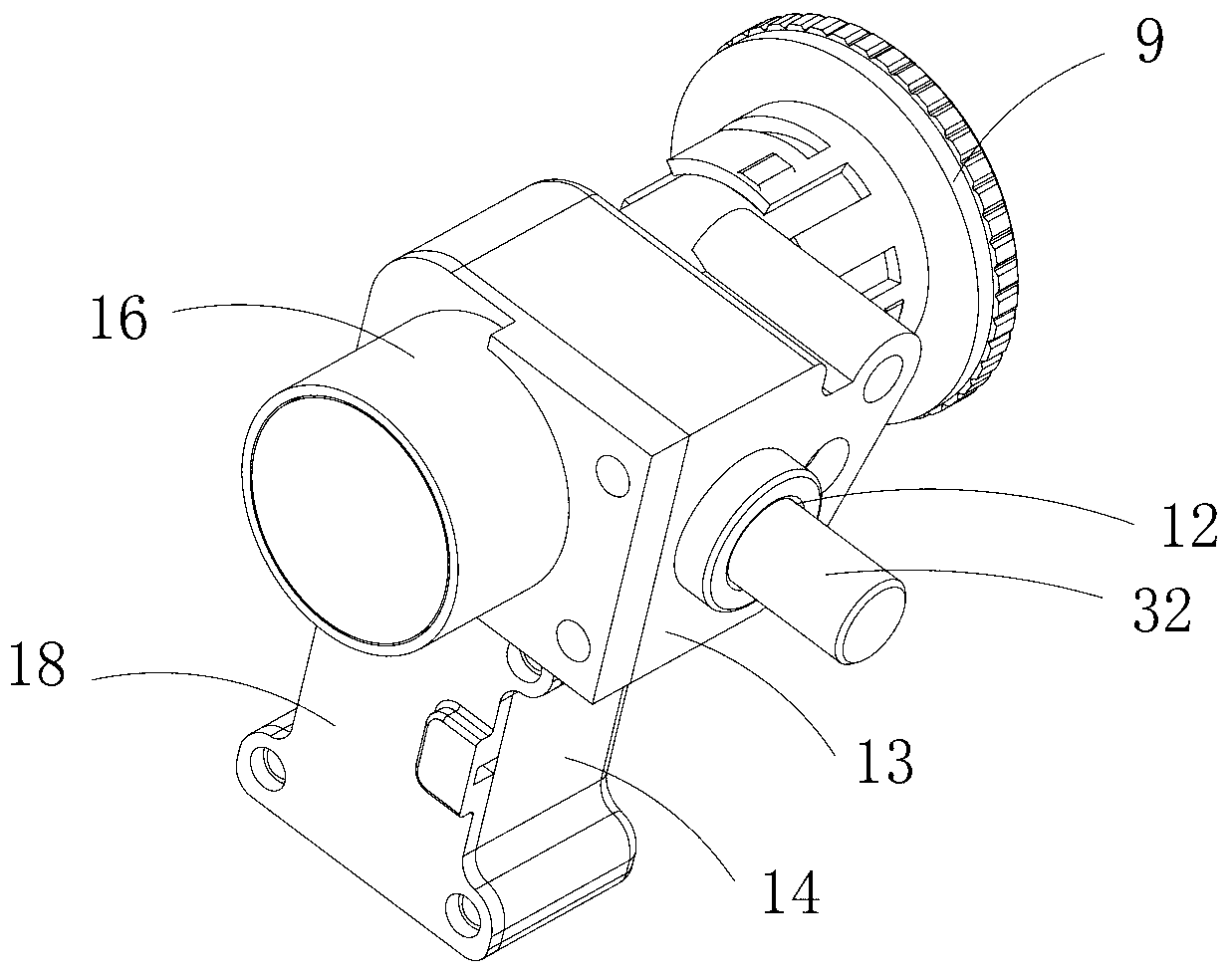
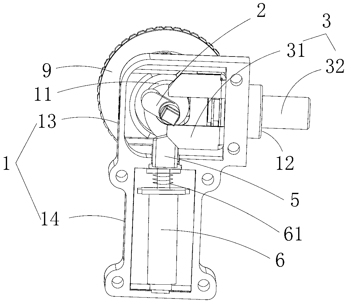
[0037] The electric anti-theft direction lock of this embodiment comprises a casing 1, a lock core 2 and a dead bolt 3, the casing 1 includes a first through hole 11 and a second through hole 12, and the lock core 2 is rotatably arranged in the first through hole 11 The lock tongue 3 is movably arranged in the second through hole 12. When the lock core 2 rotates, the lock core 2 drives the lock tongue 3 to move outward or inward along the length direction of the second through hole 12. The electric anti-theft direction lock It also includes a limiter 5, a drive mechanism 6 that drives the limiter 5 to retract, a control unit 7 connected to the drive structure, and a remote controller 8 that sends a control signal to the ...


PUM


Abstract

The invention discloses an electric anti-theft directional lock. The electric anti-theft directional lock comprises a shell 1, a lock cylinder 2 and a lock tongue 3. The shell 1 comprises a first through hole 11 and a second through hole 12. The lock cylinder 2 can be rotably arranged in the first through hole 11. The lock tongue 3 can be movably arranged in the second through hole 12. When the lock cylinder 2 rotates, the lock tongue 3 is driven by the lock cylinder 2 to move outwards or move inwards in the length direction of the second through hole 12. The electric anti-theft directional lock further comprises a limiting piece 5, a drive mechanism 6 driving the drive limiting piece 5 to retract, a control unit 7 connected with the drive mechanism and a remote control 8 which sends a control signal to the control unit 7 and ensures that the drive mechanism is driven by the control unit to move. A first elastic piece 61 is arranged between the limiting piece 5 and the drive mechanism 6. The limiting piece 5 stretches outwards under the action of the elasticity of the first elastic piece 61 and limits the lock tongue 3, and after the remote control 8 sends the control signal, the limiting piece 5 is driven by the drive mechanism 6 to retract, and limiting of the lock tongue 3 is relieved. The electric anti-theft directional lock has the advantages of being good in anti-theft effect.

Description

technical field [0001] The invention relates to a lockset, more specifically, to an electric anti-theft direction lock. Background technique [0002] In daily life, when consumers use two-wheeled electric vehicles, two-wheeled motorcycles and other motor vehicles, before leaving the motor vehicle, consumers generally use the steering lock to power off the vehicle and lock the handlebars. However, in recent years, the phenomenon of car theft Increasingly rampant, some car thieves use tools such as self-provided keys or iron wires to open the steering lock, resulting in a more serious phenomenon of car loss in life, causing many consumers to suffer losses. This is mainly due to the traditional direction lock, which can be locked by turning the lock cylinder or unlocked by turning the lock cylinder, so car thieves use tools such as self-provided keys or iron wires to open the lock cylinder to steal the car. It can be seen that the anti-theft effect of the traditional direction...

Claims


Application Information

Patent Timeline
Patent Type & Authority Applications(China)
IPC IPC(8): E05B47/06E05B49/00
Inventor 孙木楚
Owner SHENZHEN TAILG ELECTRIC VEHICLE
Why Eureka
Try Eureka