Underground space top structure and design method thereof

A technology of underground space and design method, which is applied in underwater structures, infrastructure engineering, hydraulic engineering and other directions to save construction time, improve the load-resisting capacity of the top structure, and ensure emergency evacuation problems.

Active Publication Date: 2020-07-24
SOUTHWEST JIAOTONG UNIV +1
View PDF7 Cites 0 Cited by
  • Summary
  • Abstract
  • Description
  • Claims
  • Application Information

AI Technical Summary

Problems solved by technology

[0003] The purpose of the present invention is to provide a top-floor structure of underground space and its design method in view of the problem that the strength of the top-floor structure of the existing urban underground space needs to be improved in the prior art, which can effectively guarantee the safety of the urban underground space

Method used


Image

  • Underground space top structure and design method thereof
  • Underground space top structure and design method thereof
  • Underground space top structure and design method thereof

Examples


Embodiment 1

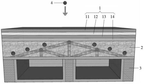
[0041] like Figure 1-2 As shown, the roof structure of an underground space according to the present invention includes a reinforcement part 1, and the reinforcement part 1 includes an energy-absorbing layer 11, a steel plate layer 12, a weak cushion layer 13 and a reinforced concrete layer sequentially connected from top to bottom. Layer 14, the reinforced concrete layer 14 is used to connect to the top of the underground space structure.

[0042]Wherein, the underground space structure includes an energy dissipation part 2 and a protection part 3, the protection part 3 is connected to the bottom of the energy dissipation part 2, the energy dissipation part 2 is connected to the bottom of the reinforced concrete layer 14, and the protection part 3 includes a cavity, which is used for emergency refuge.

[0043] Using the roof structure of the underground space according to the present invention, the energy-absorbing layer 11, the steel plate layer 12, the weak cushion layer ...

Embodiment 3

[0068] In a further embodiment of the present invention, we verify the feasibility of the large energy that the above-mentioned top-level structure can consume and its design method through a calculation example. In this embodiment, the national standard formula is used to calculate energy: energy (J)=(average strength ×thickness×width (mm)) / 1002. Unit: kg-cm / cm 2 Meaning: The ratio of the energy absorbed by the sample during the impact failure process to the original cross-sectional area. The origin of 1002: Because 1 Joule = 10.2kg.cm, it is necessary to convert the energy unit from kg.m to kg.cm, that is, because the unit of thickness and width of 10.2kg.cm is mm, the unit needs to be converted to cm, because when calculating Divided by the area, it needs to be enlarged by 100 times, so 10.2kg.cm×100=1002.

[0069] Assume that the thickness of each layer of the top layer of the underground space is 1m, and the total thickness is 4m. The length is 5m and the width is 3m, ...


PUM


Abstract

The invention discloses an underground space top structure and a design method thereof. The structure comprises a reinforcing part, the reinforcing part comprises an energy absorbing layer, a steel plate layer, a weak cushion layer and a reinforced concrete layer which are connected in sequence from top to bottom, the reinforced concrete layer is used for being connected to the top of an underground space structure, through vertical segment-by-segment gradual type load bearing and energy consuming by the energy absorbing layer, the steel plate layer, the weak cushion layer and the reinforced concrete layer, the strength of the top structure is effectively improved, the load resisting capacity of the top structure is improved, the phenomenon that during load resistance by an upper section of an underground structure, deforming is too large is avoided, the safety barrier of the underground structure is effectively reinforced, the construction time of a structure system can be saved, mounting and dismounting are facilitated, the construction efficiency is improved, the emergency refuge taking of the underground space can be effectively ensured, and the safety of the underground spacecan be improved.

Description

technical field [0001] The invention relates to the field of emergency refuge, in particular to an underground space roof structure and a design method thereof. Background technique [0002] In the previous urban underground space structure system, the planning and design of emergency refuge space, the ability to deal with urban air defense and urban emergency evacuation capabilities are far from sufficient, the functions of urban protection and disaster prevention have not been unified, and a city under unified leadership has not yet been formed. Comprehensive air defense and disaster prevention system to realize the integration and integration of urban air defense and disaster prevention. As a result, the safety of the urban underground space has been seriously affected, and it is necessary to find an effective top-level structure of the underground space. Contents of the invention [0003] The object of the present invention is to provide an underground space top struc...

Claims


Application Information

Patent Timeline
Patent Type & Authority Applications(China)
IPC IPC(8): E02D29/045E04H9/12G06F30/13
CPCE02D29/045E04H9/12
Inventor 肖清华雷升祥熊强李文胜李庆韩翔宇袁文朱洪江丁猛何亚涛邱泽民吴东宇李聪明陈乔枫赵伟
Owner SOUTHWEST JIAOTONG UNIV
Why Eureka
Try Eureka