A Device for Preventing Reactor Bombing Rod Accidents

A technology for reactors and sticks, which is applied in the fields of reactors, nuclear reaction control, nuclear power generation, etc., can solve the problems of not being able to fully guarantee that the pressure cover is not ruptured and damaged, without the safety facilities for sticks, and increasing the reactivity, so as to achieve automation and safety. High, reduce the range of changes, and improve the effect of reliability

Active Publication Date: 2018-07-24
NORTH CHINA ELECTRIC POWER UNIV (BAODING)
View PDF6 Cites 0 Cited by
  • Summary
  • Abstract
  • Description
  • Claims
  • Application Information

AI Technical Summary

Problems solved by technology

The pressure-bearing casing of the control rod drive mechanism is the pressure-bearing boundary of the reactor. Under accident conditions, the pressure-bearing casing may rupture, and the high-pressure coolant in the primary circuit will rush the control rods out of the reaction zone, resulting in a rod-popping accident, which will reduce the reactivity. increase, causing the core to melt, so effective measures should be taken to prevent the occurrence of bombing rod accidents
[0004] At present, the method of increasing the strength of the pressure housing is generally used to prevent the rupture of the pressure housing, to ensure the balance between the pressure of the driving mechanism and the pressure of the core, and to prevent the coolant from being sprayed out and causing the stick accident. This method cannot completely guarantee that the pressure housing will not be ruptured or damaged; The method of increasing the weight of the control rod assembly or using counterweights makes the control rods quickly fall into the core while preventing the core from popping up. This method is limited by the space and material density. If the breach in the pressure-bearing shell is large enough, the coolant spray The outflow is sufficient, and there is also the possibility of a stick accident. There is no special safety facility that can effectively control the accident of the stick

Method used


Image

  • A Device for Preventing Reactor Bombing Rod Accidents
  • A Device for Preventing Reactor Bombing Rod Accidents
  • A Device for Preventing Reactor Bombing Rod Accidents

Examples


Embodiment Construction

[0057] The present invention will be further described in detail through the drawings and examples below. Through these descriptions, the features and advantages of the present invention will become more apparent.

[0058] The word "exemplary" is used exclusively herein to mean "serving as an example, embodiment, or illustration." Any embodiment described herein as "exemplary" is not necessarily to be construed as superior or better than other embodiments. While various aspects of the embodiments are shown in drawings, the drawings are not necessarily drawn to scale unless specifically indicated.

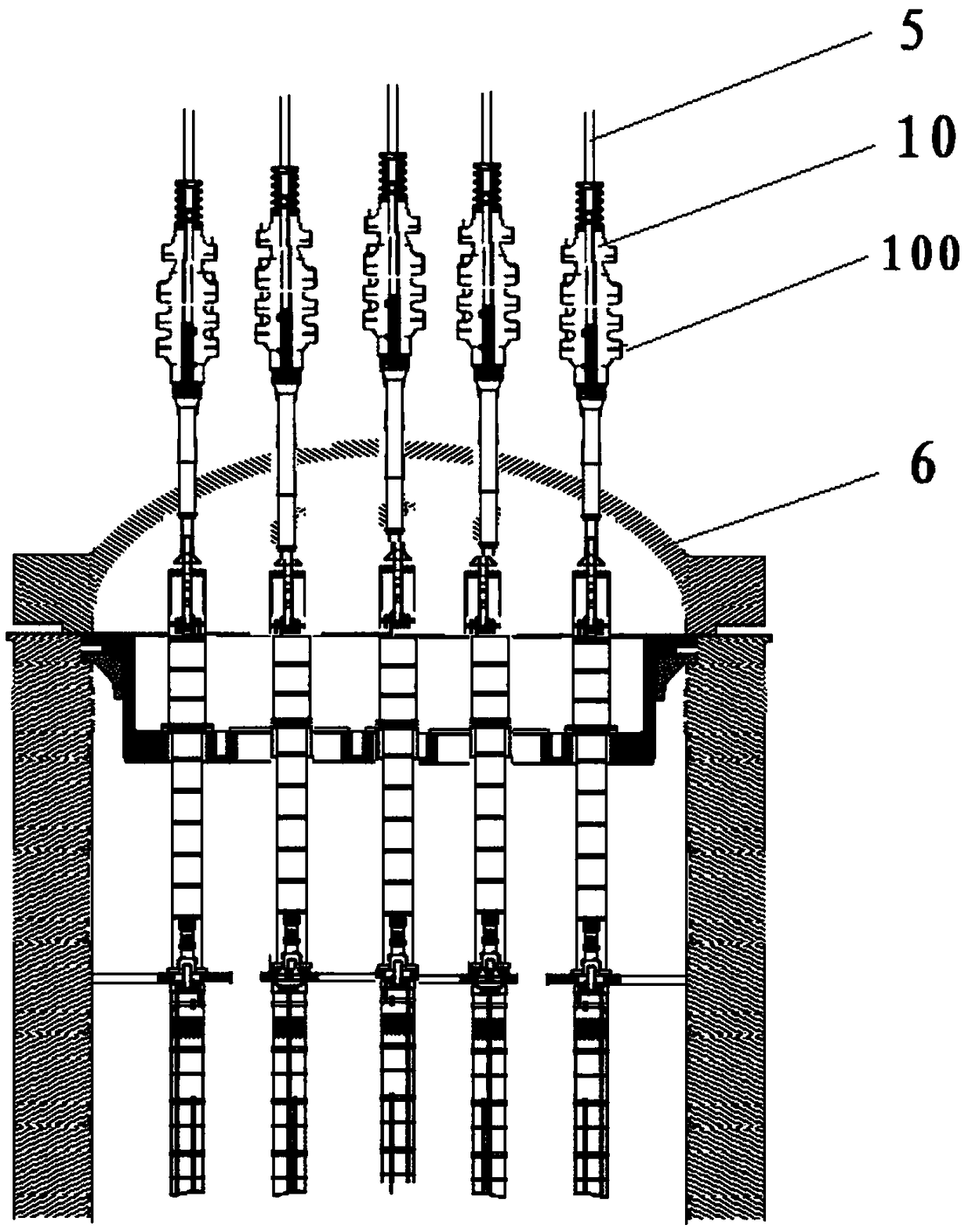
[0059] According to a kind of device that the present invention provides to prevent the reactor from bouncing a rod accident, its relative position with the reactor pressure vessel 6 is as follows: figure 1 As shown, it is located at the external upper end of the reactor pressure vessel 6 and placed at the lower part of the control rod driving mechanism 10 .

[0060] In a preferr...


PUM


Abstract

The invention discloses a device for preventing a reactor from rod ejection accidents. The device comprises a pawl component (1), a control component (2) and a cable component (3), wherein the device is positioned at the lower part of a control rod driving mechanism (10); the control rod driving mechanism (10) is arranged around a driving shaft (5) and is positioned at the upper end of the outer part of a reactor pressure container (6); the cable component (3) is used for providing power to the control component (2); the control component (2) is used for generating electromagnetic induction and displaces to drive the pawl component (1) to move, and the pawl component (1) can be meshed or dissociated from the driving shaft (5). The device sufficiently utilizes the structure of a conventional driving mechanism, the reactor can be prevented from rod ejection accidents, and security curtains can be provided for the control rod driving mechanism.

Description

technical field [0001] The invention relates to the fields of nuclear power safety and mechanical equipment, and is especially suitable for a control rod control system. Background technique [0002] Nuclear power is an efficient and clean new energy. Compared with traditional thermal power generation, nuclear power has the characteristics of less raw materials, high efficiency and no pollution. However, once a nuclear accident occurs, it will lead to very serious consequences, and even cause a fatal blow to society. Therefore, it is crucial to ensure the safe operation of nuclear power plants and prevent core meltdown. [0003] When the reactor is in normal operation, the control rod drive mechanism completes the lifting and falling of the control rod assembly in the core to realize reactivity control. In case of emergency shutdown or loss of external power supply, the control rods fall into the core by gravity to ensure safe shutdown. The pressure-bearing casing of the ...

Claims


Application Information

Patent Timeline
Patent Type & Authority Patents(China)
IPC IPC(8): G21C7/14
CPCG21C7/14Y02E30/30
Inventor 周涛李子超周蓝宇张晗李兵田晓瑞陈娟
Owner NORTH CHINA ELECTRIC POWER UNIV (BAODING)
Why Eureka
Try Eureka