Led backlight driving circuit, liquid crystal display device and a driving method

A technology of backlight drive circuit and LED light bar, which is applied in the direction of electrical components, static indicators, instruments, etc., can solve the problem of large heat loss, achieve the effect of reducing energy loss and increasing conversion efficiency

Active Publication Date: 2016-04-13
TCL CHINA STAR OPTOELECTRONICS TECH CO LTD
View PDF5 Cites 2 Cited by
  • Summary
  • Abstract
  • Description
  • Claims
  • Application Information

AI Technical Summary

Problems solved by technology

[0003] The conversion efficiency of the boost circuit is the highest when working at full load, and its conversion efficiency decreases as the output power decreases. The heat loss of the circuit is large, and the conversion efficiency is lower than that of the single-channel boost circuit when it is fully loaded.

Method used


Image

  • Led backlight driving circuit, liquid crystal display device and a driving method
  • Led backlight driving circuit, liquid crystal display device and a driving method
  • Led backlight driving circuit, liquid crystal display device and a driving method

Examples


Embodiment 1

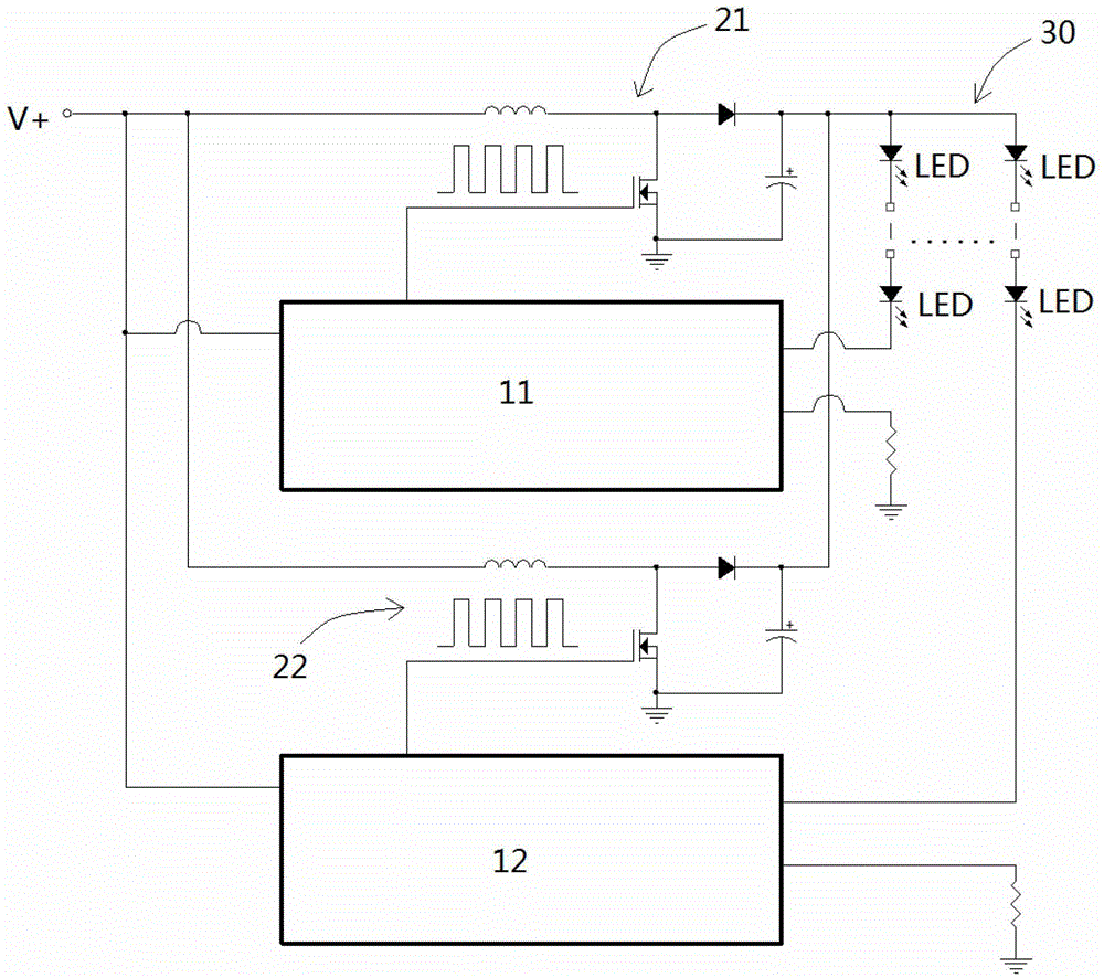
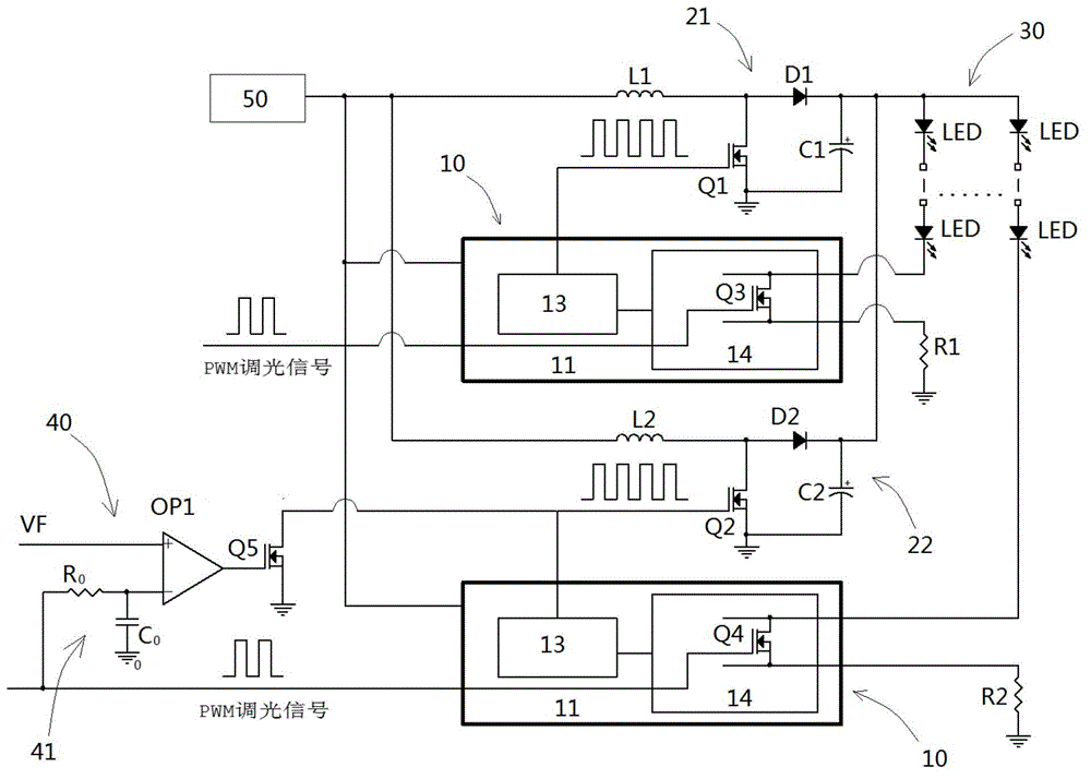
[0045] Such as figure 2 As shown, the LED backlight driving circuit includes a power module 50, an LED light bar 30, and a constant current driver chip 10 for adjusting the brightness of the LED light bar 30, and the constant current driver chip 10 is coupled with a PWM dimming signal; the power module 50 and the LED light bar N booster modules arranged in parallel are connected in series between the light bars 30 , and the control terminals of 1˜(N−1) booster modules are coupled with a comparison module 40 . The LED backlight driving circuit in this embodiment includes a first boost module 21 and a second boost module 22 , wherein a comparison module 40 is coupled to the control terminal of the second boost module 22 .

[0046] The comparison module 40 includes a comparator OP1, the non-inverting input terminal of the comparator OP1 is coupled with a reference voltage VF, and the inverting input terminal is coupled with a conversion unit 41 that converts the PWM dimming sign...

Embodiment 2

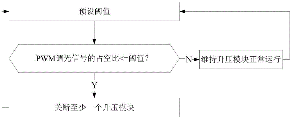
[0055] The invention also discloses a driving method of an LED backlight driving circuit. The LED backlight driving circuit includes a power supply module, an LED light bar, and a constant current driving chip for adjusting the brightness of the LED light bar. The constant current driving chip is coupled with PWM dimming Signal; N booster modules arranged in parallel are connected in series between the power module and the LED light bar. Such as image 3 As shown, the driving method of the LED backlight driving circuit includes:

[0056] A. Preset a duty cycle threshold of a PWM dimming signal;

[0057] B. Detect the duty cycle of the PWM dimming signal, and when the duty cycle is less than the preset threshold, go to step C; otherwise, go to step D;

[0058] C. Control at least one boost module to shut down; return to step A;

[0059] D. Maintain the normal operation of the booster module; return to step A;

[0060] The N is an integer greater than or equal to 2.

[0061...


PUM


Abstract

An LED backlight driving circuit comprises a power supply module, an LED light bar, and a constant-current driving chip used for adjusting the brightness of the LED light bar. The constant-current driving chip is coupled to a PWM dimming signal. N step-up modules disposed in parallel are connected in series between the power supply module and the LED light bar. Control ends of 1 to n-1 step-up modules are coupled to comparison modules. When the duty cycle of the PWM dimming signal is less than a preset threshold, each comparison module drives a corresponding step-up module to be turned off. N is an integer greater than or equal to 2.

Description

technical field [0001] The invention relates to the field of liquid crystal display, and more specifically relates to an LED backlight driving circuit, a liquid crystal display device and a driving method. Background technique [0002] LCD TVs include LCD panels and backlight modules. The backlight modules mostly use LEDs as the backlight source. Multiple LED lamp beads are connected in series to form LED light bars, which are driven and displayed by the backlight drive circuit; the brightness of the backlight required by large-size LCD TVs High, need to use multi-series parallel LED light strips, the output power of the entire backlight module is very large, the backlight drive circuit using a single boost circuit cannot provide matching power, and a dual boost circuit is required to drive the LED in parallel Light. like figure 1 As shown, the external power supply V+ is connected to the first boost circuit 21 and the second boost circuit 22 at the same time, and the LED ...

Claims


Application Information

Patent Timeline
Patent Type & Authority Patents(China)
IPC IPC(8): G09G3/34G09G3/36
CPCG09G3/3406G09G2320/064H05B45/38H05B45/46
Inventor 张华黎飞
Owner TCL CHINA STAR OPTOELECTRONICS TECH CO LTD
Why Eureka
Try Eureka