Light emitting block constant current driving circuit

A drive circuit and constant current source technology, applied in the field of constant current source drive circuits, can solve the problems of affecting production efficiency, unable to meet model requirements, low accuracy, etc., and achieve simple structure, high inherent reliability, and strong pertinence. Effect

Inactive Publication Date: 2015-05-27
SHANGHAI AVIATION ELECTRIC
View PDF3 Cites 2 Cited by
  • Summary
  • Abstract
  • Description
  • Claims
  • Application Information

AI Technical Summary

Problems solved by technology

This method greatly affects the production efficiency, and the accuracy rate is not high, which cannot meet the model requirements

Method used


Image

  • Light emitting block constant current driving circuit
  • Light emitting block constant current driving circuit
  • Light emitting block constant current driving circuit

Examples


Embodiment Construction

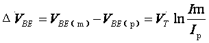
[0014] Taking the NPN transistor as an example, when the transistor meets the following three requirements, the collector current Ic in the transistor is related to the base-emitter voltage VBE, which is determined by formula (1).

[0015] a) The collector potential must be higher than the emitter potential;

[0016] b) Base-emitter forward bias, base-collector reverse bias;

[0017] c) The transistor works under the rated voltage and power consumption.

[0018] …… (1)

[0019] Where VT=kT / q=25.3mV, at room temperature (20°C), q is an electronic charge (1.6×10 -19 library), k is the Boltzmann constant (1.38×10 -23 J / K), T is the thermodynamic temperature in K (1K≈1°C+273.16), IS is the reverse saturation current of the emitter junction of the transistor (depending on the thermodynamic temperature T).

[0020] Equation (1) is called the Ebers-Moll equation, which shows that at a certain temperature, the transistor collector current Ic is controlled by the base-emitter v...


PUM


Abstract

The invention discloses a constant current source driving circuit with an adjustable output current value. The constant current source driving circuit is characterized in that each mirror image branch comprises a first triode and a second triode; the collector of the first triode of each mirror image branch is connected with the emitter of the second triode; the base of the first triode of each mirror image branch is connected with that of a control end triode; the emitter of the first triode of each mirror image branch is connected with the positive end of a power supply through a resistor; the emitter of the second triode of each mirror image branch is connected with the base of the control end triode; the collector of the second triode of each mirror image branch is grounded through the resistor. On the basis of an Ebers-Moll equation and a mirror image current source technology, multiple paths of light emitting block driving current output are achieved and are independent of one another, and the current value of each path can be configured gradually through the resistor. The constant current source driving circuit can be used for constant-current driving of aircraft lamp light alarm equipment and built-in lighting equipment.

Description

technical field [0001] The invention relates to a constant current source drive circuit with adjustable output current value. Background technique [0002] In order to meet the requirements of modern combat missions, the model has more and more stringent requirements for the flexible configuration of signal light brightness. This means that modern aircraft have higher and higher requirements for light warning system and light-emitting blocks in the lighting system, such as high-brightness readability during the day, low-brightness stability at night, brightness consistency, dimming uniformity, and compliance with light performance parameters. . [0003] In order to meet these requirements, most of the current light-emitting block driving circuits are voltage-driven, and the light-emitting blocks are driven by converting voltage into current through resistors. Since different batches of light-emitting diodes have different voltage-brightness relationships, in order to meet ...

Claims


Application Information

Patent Timeline
Patent Type & Authority Applications(China)
IPC IPC(8): H05B37/02
Inventor 杨滨
Owner SHANGHAI AVIATION ELECTRIC
Why Eureka
Try Eureka