[0023] The present invention will be further explained below in conjunction with specific embodiments. It should be understood that these embodiments are only used to illustrate the present invention and not to limit the scope of the present invention. In addition, it should be understood that after reading the teachings of the present invention, those skilled in the art can make various changes or modifications to the present invention, and these equivalent forms also fall within the scope defined by the appended claims of this application.
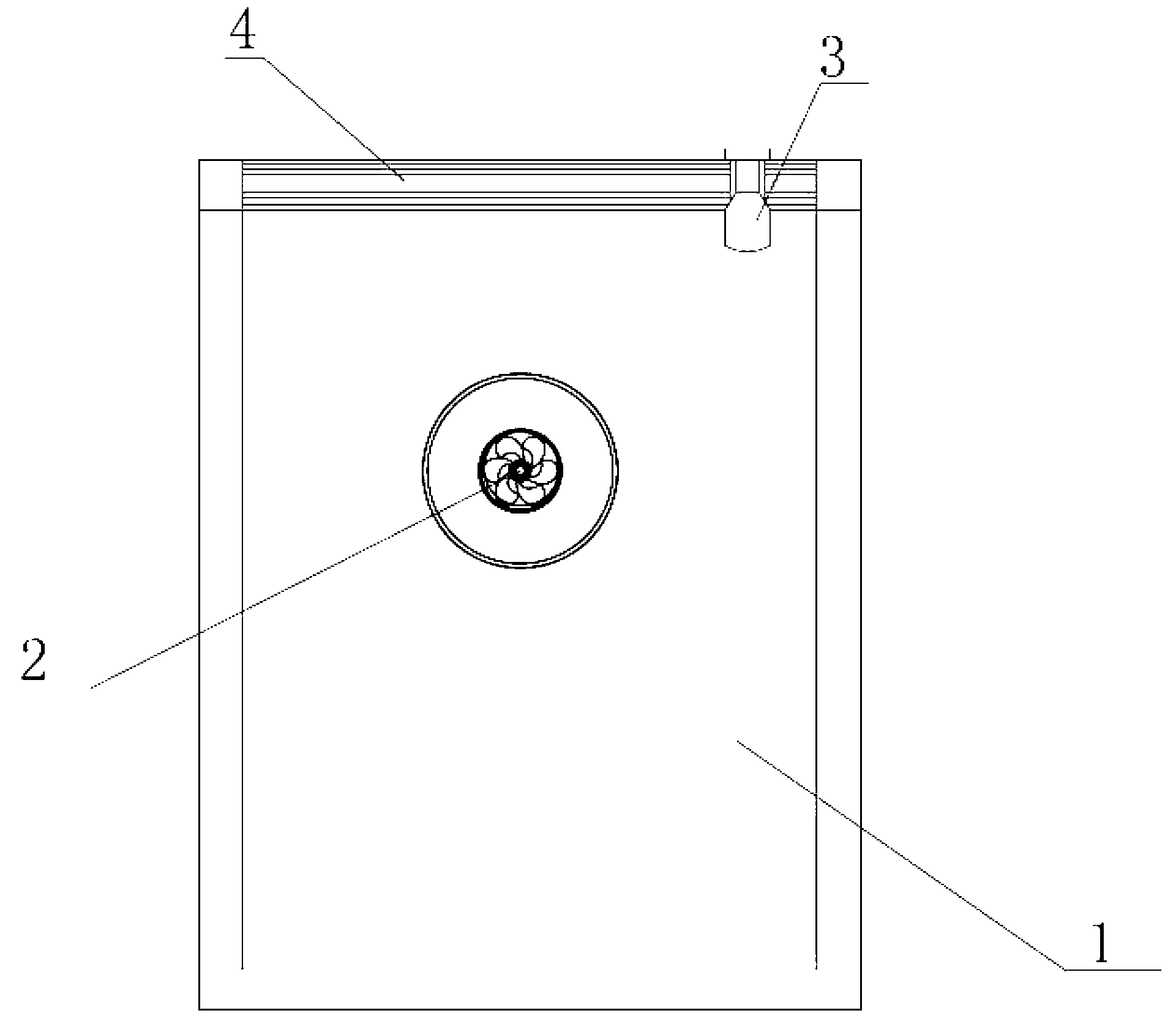
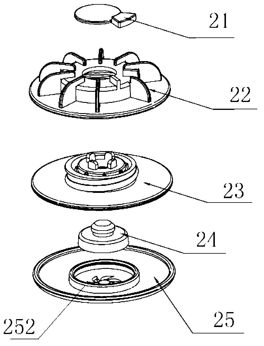
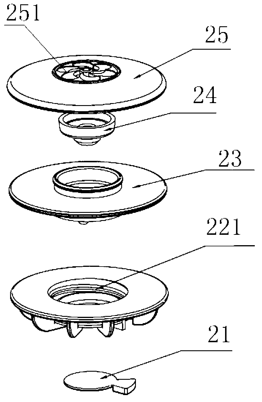
[0024] Such as Figure 1-11 As shown, the embodiment of the present invention relates to a sealed file bag equipped with a two-way air valve, comprising a zipper 4, an engineering plastic bag 1 and a zipper 3, and a zipper 4 is arranged at the upper opening of the engineering plastic bag 1. The engineering plastic bag 1 is made of engineering plastic with flame retardant and coated with an aluminum layer on the surface. A two-way air valve 2 is installed on one side wall, and the zipper 4 is installed with a side wall that can slide left and right. The pull buckle 3, the two-way air valve 2 includes a valve seat 22, a valve cover 25 and a gasket 24, a valve cover 25 is installed on one side of the valve seat 22, the valve cover 25 and the valve seat 22 A gasket 24 is arranged in between, a movable sealing sheet 21 is installed in the middle of the other side of the valve seat 22, a central body 23 is installed between the gasket 24 and the valve seat 22, and the valve seat 22 A connecting thread 221 is arranged on the side wall of the inner hole connected to the central body 23, one side of the central body 23 is arranged with a threaded post 232 matching the connecting thread 221, and a limit guide post 233 is arranged on the other side. A support body 235 connected with the central body 23 is arranged inside the threaded column 232. The support body 235 has a circular hole in the center and a plurality of top blocks 231 are evenly arranged along the circular hole. The connecting part of the 235 and the central body 23 has a plurality of air vents 234 evenly opened along the circumference, and a suction hole 251 is opened in the middle of the valve cover 25.
[0025] The zipper 4 is a double-track concave-convex zipper. On the inner walls of both sides, C-shaped moldings 41 and moldings 42 that match the C-shaped grooves 41 are arranged on the inner walls. The C-shaped moldings 41 and 42 on the opposite sidewalls The installation position is opposite.
[0026] The movable sealing sheet 21 includes a rubber disc 211 and a sector-shaped card board 212 connected to one side thereof.
[0027] The valve seat 22 is connected to one side of the bag wall of the engineering plastic bag 1, and a boss 223 is arranged on the side facing the inside of the bag. The outer edge of the boss 223 is evenly arranged with a ring of reinforcing plates 222 along the circumference. The upper end of the boss 223 is provided with a pair of limiting protrusions 225 matched with the fan-shaped clamping plate 212, and a central hole with a diameter smaller than the rubber disc 211 is opened in the middle of the boss 223. The fan-shaped clamping plate 212 is embedded between a pair of limiting protrusions 225, and a rubber disc 211 covers the central hole.
[0028] The pull buckle 3 includes a U-shaped body 31, the middle of its inner side wall is symmetrically arranged with an extrusion protrusion 34, and an olive-shaped bead 311 is symmetrically arranged at the opening of the lower end of the U-shaped body 31. The extrusion The pressing protrusion 34 is an arc-shaped protrusion, and the pressing protrusion 34 is divided into an upper half 341 and a lower half 342, and the height of the upper half 341 is greater than the lower half 342.
[0029] In this embodiment, first open the zipper 4 of the file bag, load the materials that need to be preserved or sterilized, and use the zipper 3 to close the zipper 4. When inflating, the valve cover 25, the sealing cushion 24 and the central body 23 are removed. Then put O 3 The output connector of the generator is connected with the connecting thread 221 of the inner hole of the valve seat 22, the working time is set, and the O 3 Generator switch, O 3 The generator works, blows air on the movable sealing sheet 21, the air pressure blows the rubber disc 211 open, and inflates the file bag, O 3 The amount of air delivery is determined by the capacity of the portfolio, and it is generally sufficient to deliver air until the portfolio is obviously bulged;
[0030] Once the set time is up, O 3 The generator stops working, remove O 3 The output connector of the generator will automatically seal the rubber disc 211 by air pressure, and wait for about 30 to 45 minutes to sterilize the data in the file bag;
[0031] After the sterilization is completed, press the two-way air valve 2 figure 2 The assembly shown is complete. At this time, the central body 23 is threadedly connected to the valve seat 22 through the threaded column 232, the top block 231 pushes the movable sealing sheet 21 apart, and the suction tube connector is aligned with the suction hole 251, and the The gas is drawn out, and the gas is sucked out through the circular hole of the support body 235 and the vent 234. As the gas is continuously sucked out, the negative pressure in the file bag becomes higher and higher, pulling the sealing cushion 24 to move to the central body 23 until the sealing cushion 24 The circular hole of the support body 235 and the vent 234 are blocked, and the suction cylinder is removed to make the file bag into a vacuum sterile state, so as to achieve the purpose of permanent preservation of the data.