Omni-directional imaging device and method

A panoramic imaging and panorama technology, applied in optics, instruments, wide-screen photography, etc., can solve the problems of difficulty in design, processing and system installation, low resolution, high price, etc., to improve pixel utilization and improve Image resolution, effect of reducing design difficulty

Active Publication Date: 2013-09-11
ZHEJIANG UNIV
View PDF7 Cites 12 Cited by
  • Summary
  • Abstract
  • Description
  • Claims
  • Application Information

AI Technical Summary

Problems solved by technology

However, due to the structure of the first reflector of the catadioptric panoramic ring lens, the light in the middle field of view is inevitably blocked by the first reflector and cannot enter the subsequent light group, resulting in a With a circular image surface, the pixels in the middle cannot be fully utilized and become blind spots
Generally speaking, the larger the circular imaging surface of the catadioptric panoramic ring lens, the larger the blind area, and the more pixels are wasted on the image sensor. This is the biggest shortcoming of the catadioptric panoramic ring lens.
[0004] On the other hand, due to the ultra-wide-angle characteristics of the catadioptric panoramic ring lens, the size of the image of an object with a large peripheral field of view on the image sensor is severely compressed, which is limited by the size of a single CCD\CMOS image sensor, especially In the current CCD\CMOS image sensor size can not be made too large, and the large-size CCD\CMOS is expensive, the severely compressed image is limited to a single CCD\CMOS image sensor, resulting in CCD\CMOS The resolution of the image at the edge of the image sensor is low, which cannot reflect the details of objects at the edge of the field of view well
[0005] Chinese invention patent CN201110331166.8 discloses a panoramic telescopic combined imaging system and method using a panoramic annular lens, using a telescope group and a panoramic annular lens located on the same optical axis to view the scene corresponding to the annular image plane through the telescope The group and the panoramic lens are enlarged and imaged in the blind area to improve the pixel utilization of a single sensor and realize the dual functions of panorama and telephoto at the same time, but the size of its imaging surface is still limited by the size of a single CCD or CMOS image sensor. Moreover, the combined design of the telescope group and the panoramic ring lens, and the rotating scanning mechanism of the telescope group have brought great difficulties to the optical and mechanical design, processing and system assembly.

Method used


Image

  • Omni-directional imaging device and method
  • Omni-directional imaging device and method
  • Omni-directional imaging device and method

Examples


Embodiment 1

[0025] Example 1 Panoramic imaging device with flat imaging surface

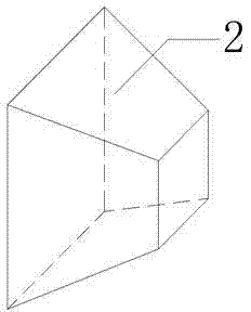
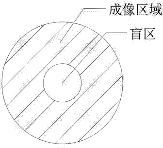
[0026] Such as image 3 As shown, the focal length obtained after optimization design is in the range of -30mm to -10mm, and the F number is in the range of 6 to 12. The catadioptric panoramic ring lens working in the visible light band has a circular image plane in the On the plane, the diameter of the outer ring of the ring size ranges from 60 to 80 mm, and the diameter of the inner ring ranges from 10 to 30 mm. The tapered optical fiber panel with a reduction ratio of 5:1, with a square at the big end and a rectangle at the small end (the ends of the big and small ends are both flat), transmits the image on the circular image plane of the catadioptric panoramic ring lens to the CCD \CMOS image sensor.

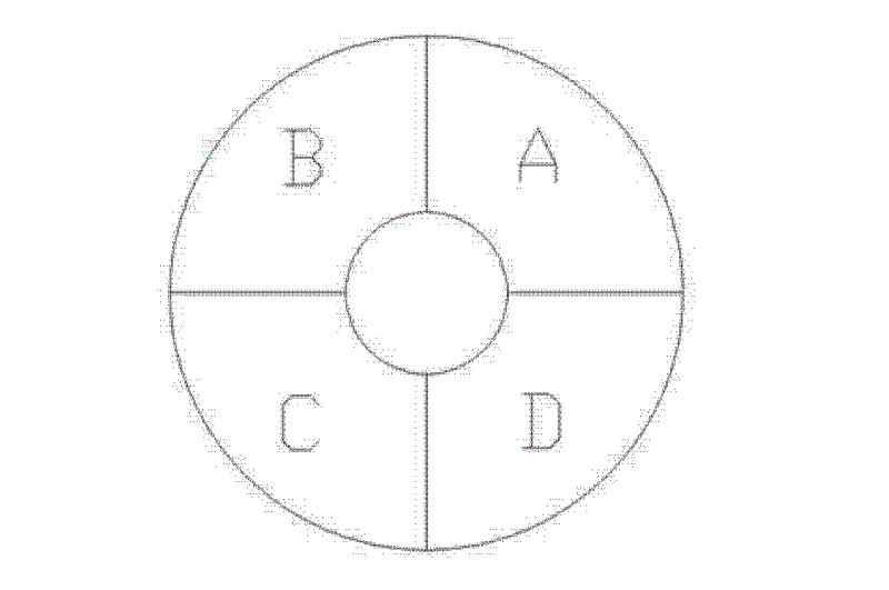
[0027] Such as Figure 4 As shown in , the circular image plane is evenly divided into four fan-shaped sub-image planes (A, B, C, D). Such as Figure 5 As shown, each sub-image area expanded into a ...

Embodiment 2

[0029] Example 2 Panoramic imaging device with spherical imaging surface

[0030] Such as Figure 6 As shown, the focal length obtained after optimization design is in the range of -30mm to -10mm, and the F number is in the range of 6 to 12. The catadioptric panoramic ring lens working in the visible light band has a circular image plane in the On a spherical surface, the diameter of the outer ring is 60-80 mm, and the diameter of the inner ring is 10-30 mm. With a reduction ratio of 5:1, the large end is fan-shaped, and the small end is rectangular (the end surface of the large end is a spherical surface, and the end surface of the small end is a flat surface). The image above is passed to the CCD\CMOS image sensor.

[0031] The circular image surface on the spherical imaging surface of the catadioptric panoramic ring lens is evenly divided into 4 fan-shaped sub-image surfaces. Each sub-image plane is matched with a tapered optical fiber panel whose large end is fan-shap...

Embodiment 3

[0033] Example 3 panoramic imaging method

[0034] The 360-degree scene around the first surface of the catadioptric panoramic ring lens is imaged by the system and a circular image surface (on a spherical or flat surface) is obtained at the rear image surface of the system, which is divided into 4 evenly Fan-shaped sub-image planes, the images on each sub-image plane are transmitted to the corresponding CCD\CMOS image sensors through the matching tapered optical fiber panels, and the images on each CCD\CMOS image sensors are expanded into The rectangular images are spliced ​​sequentially according to their order on the circular imaging surface to obtain a rectangular panoramic image. Finally, the panoramic image is displayed by the image display unit.


PUM


Abstract

The invention discloses an omni-directional imaging device and method. The omni-directional imaging method comprises the steps of: dividing a circular big imaging surface formed by a specially designed long-focus big imaging surface reflex type panorama annular lens on a plane or a spherical surface into multiple sector-shaped sub-imaging surfaces averagely; delivering each sub-imaging surface or each expanded sub-imaging surface to a corresponding image sensor through a conical optical fiber panel with the size matching with that of each sub-imaging surface; unfolding the images received by all the image sensors into rectangular images and splicing the images according to the sequence thereof on the circular imaging surface so as to obtain an omni-directional image by utilizing an image processing unit; and finally sending the omni-directional image to the display unit for displaying. As the conical optical fiber panel and the long-focus big imaging surface reflex type omni-directional annular lens are combined, real-time 360-degree panorama omni-directional imaging of a big imaging surface is realized; as multiple image sensors are utilized for image splicing, a bigger image surface can be obtained; and an image resolution rate of an edge part of a field of view can be increased.

Description

technical field [0001] The present invention relates to a panoramic imaging device and method, in particular to a panoramic ring imaging device and method. Background technique [0002] Optical fiber panel refers to a plate-shaped image transmission element whose thickness is smaller than the cross section. It is made of tens of millions of regular optical fiber composite filaments closely arranged and then processed by melting, pressing, cutting and other processes. The input and output ends of the optical fiber panel are in the Geometrically one-to-one correspondence, each optical fiber transmits an image point, thus playing the role of image transmission. Optical fiber cone, that is, tapered optical fiber panel, is a rectangular or cylindrical optical fiber panel blank of a certain length, which is drawn into a cone shape by special heating and drawing equipment, and then after annealing, it is cut into different magnifications according to different magnifications. coni...

Claims


Application Information

Patent Timeline
Patent Type & Authority Applications(China)
IPC IPC(8): G03B37/00G02B17/08
Inventor 周向东黄治白剑
Owner ZHEJIANG UNIV
Why Eureka
Try Eureka