Switching apparatus

A technology of switchgear and switch lever, which is applied in the field of electrical switchgear to achieve the effect of improving safety

Active Publication Date: 2013-09-11
SIEMENS AG
View PDF6 Cites 1 Cited by
  • Summary
  • Abstract
  • Description
  • Claims
  • Application Information

AI Technical Summary

Problems solved by technology

This situation involves a greater risk, since the switch lever in the OFF position implies a non-existent safety situation, ie a circuit without current.

Method used


Image

  • Switching apparatus
  • Switching apparatus
  • Switching apparatus

Examples


Embodiment Construction

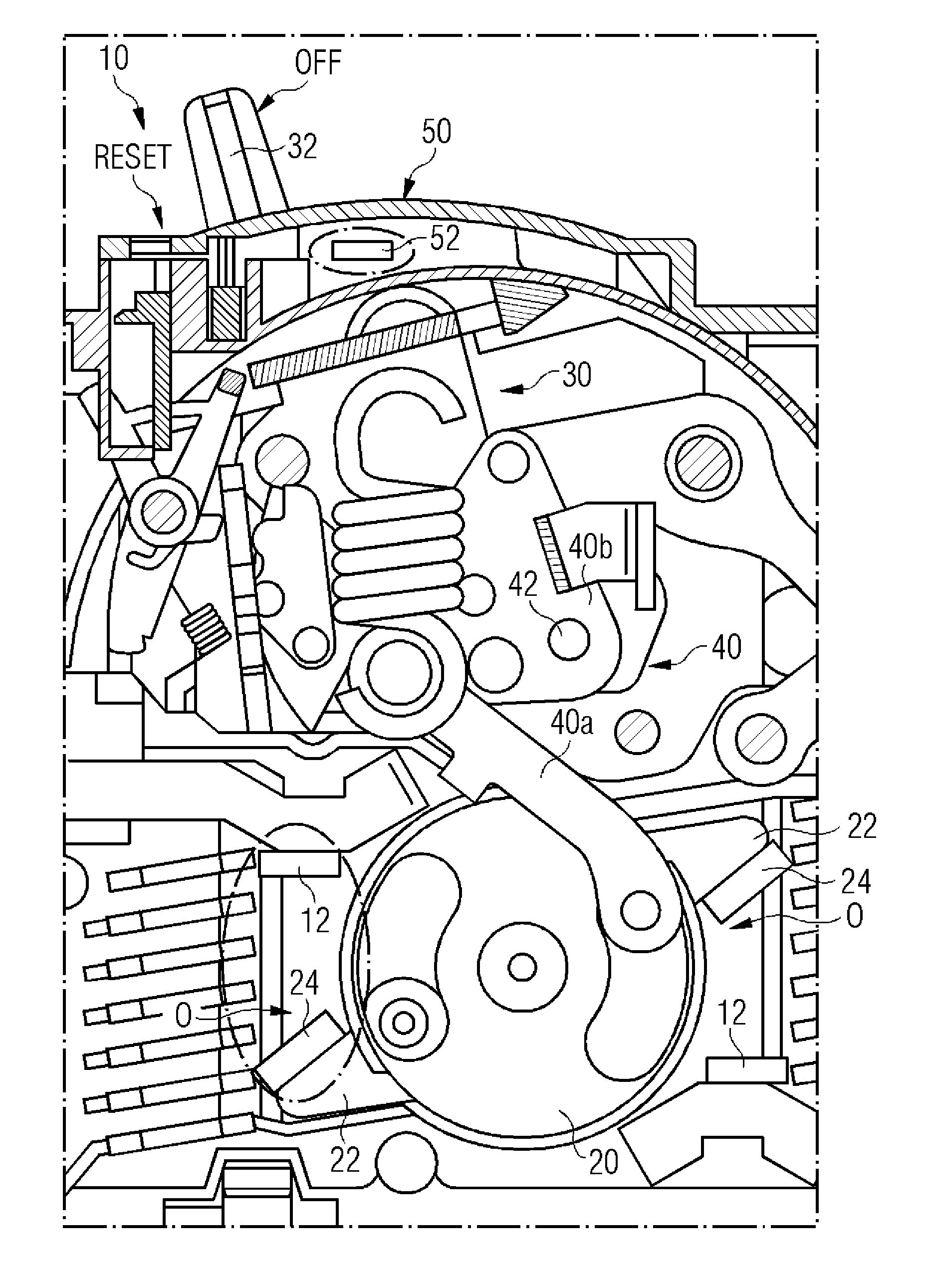
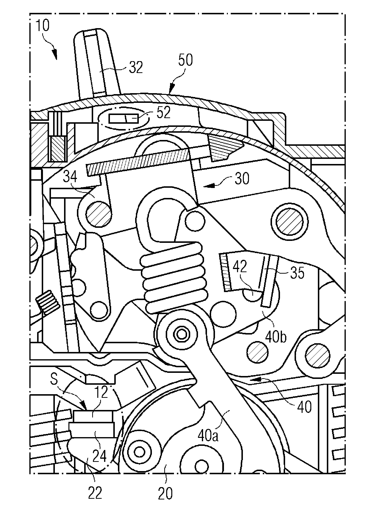
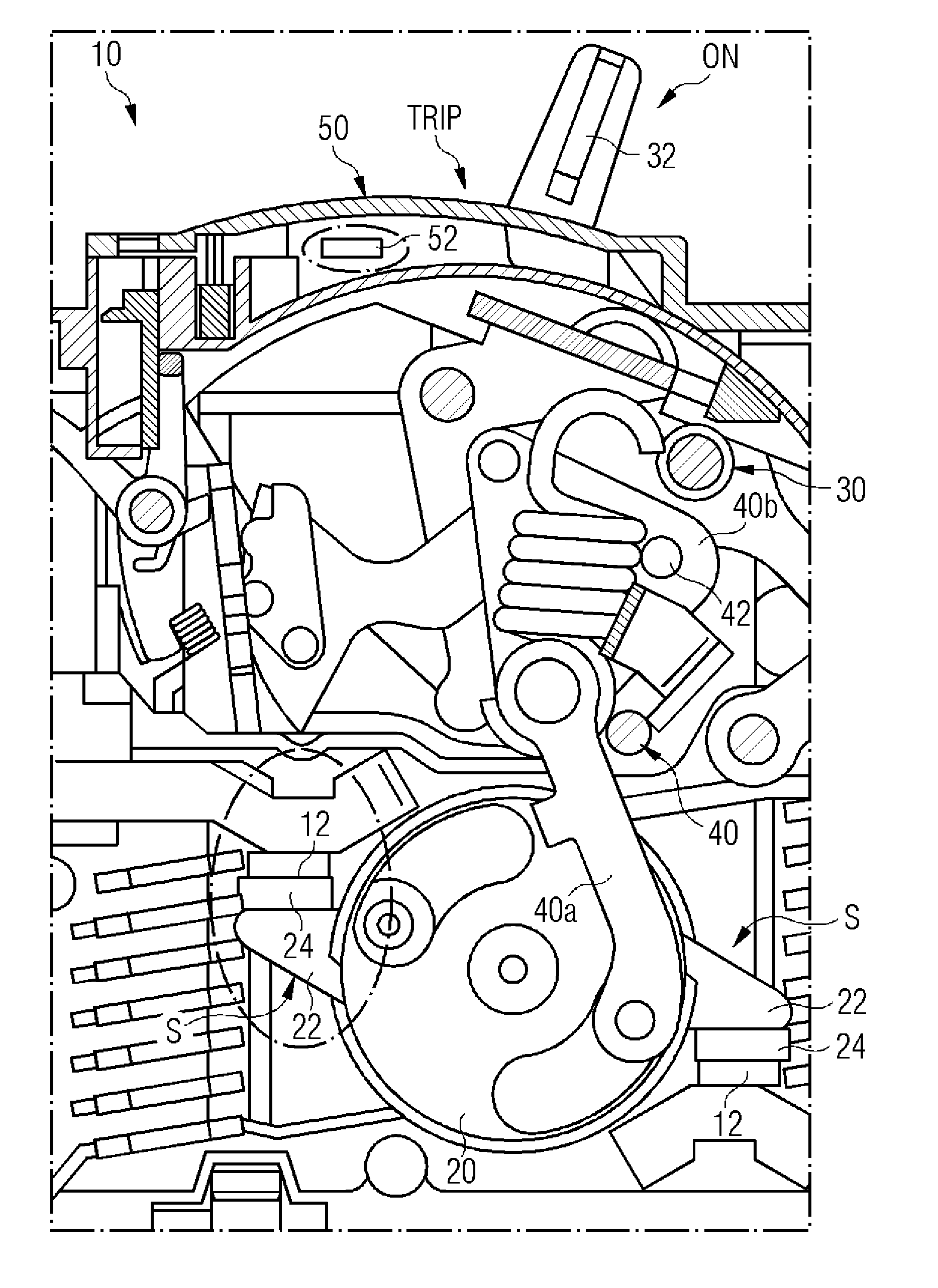
[0050] Figures 1 to 3 An embodiment of a switching device 10 according to the invention is shown. In principle the components of this embodiment are all the same. The switching device 10 therefore has a rotor housing 20 which is provided with two contact arms 22 . The contact arms are arranged on opposite sides of the rotor housing 22 and each have a movable contact 24 . exist figure 1 In this case, ie in the OFF position of the switching lever 32 , the movable contact 24 is separated from the stationary contact 12 opposite it, so that the rotor housing is in the disconnected position O. exist figure 2 The rotor housing 20 is rotated in such a way that the movable contact 24 is arranged in conductive contact with the stationary contact 12 and the rotor housing 20 is thus in the closed position S .

[0051] In addition, the switching device 10 according to the invention has a switching unit 30 . The switching unit 30 has as a main component a switching lever 32 which p...


PUM


Abstract

A switching apparatus for an electrical switching device, especially for a compact circuit breakers, is disclosed, including a rotor housing that can be rotated between an open position and a closed position; at least one contact arm with a moving contact; and a switching unit with a switching lever, movable between an ON position and an OFF position, a switching frame, and a lever mechanism in functional contact with the switching frame and the rotor housing such that movement of the switching lever into the ON position allows the rotor housing to be moved into the closed position and movement of the switching lever into the OFF position allows the rotor housing to be moved into the open position. The lever mechanism includes at least one stop, configured to prevent movement of the switching lever into the OFF position, independently of the movement of the rotor housing, when the rotor housing is in the closed position.

Description

technical field [0001] The invention relates to a switching device for an electrical switching device, in particular a compact circuit breaker, and to such an electrical switching device. Background technique [0002] Switching devices for electrical switching devices and such electrical switching devices are known in principle. In order to be able to make and break an electrical circuit, such switching devices often have a rotatable rotor housing, which can be rotated between an open position and a closed position. In the closed position, the contacts are electrically conductively connected to each other, while in the open position they are separated from each other with insulation. In addition, known switching devices provide a switching unit which can be moved by means of a switching lever at least between an ON position and an OFF position. A linkage is often provided between the switch unit and the rotatable rotor housing, which linkage converts movement between an ON...

Claims


Application Information

Patent Timeline
Patent Type & Authority Applications(China)
IPC IPC(8): H01H3/46
CPCH01H1/2058H01H71/501H01H71/521H01H73/045H01H71/525H01H23/02H01H71/526
Inventor P.奈曼M.佩特拉塞克
Owner SIEMENS AG
Why Eureka
Try Eureka