Apparatus and method for finFET

A cloak and isolation region technology, applied in the field of FinFET devices, can solve the problems that the gate cannot completely control the channel region, and the gate cannot substantially close the channel region.

Active Publication Date: 2013-09-11
TAIWAN SEMICON MFG CO LTD
View PDF7 Cites 13 Cited by
  • Summary
  • Abstract
  • Description
  • Claims
  • Application Information

AI Technical Summary

Problems solved by technology

However, as the size of semiconductor devices continues to shrink, due to the short-channel leakage effect, the gate cannot fully control the channel region, especially the part of the channel region far away from the gate...

Method used


Image

  • Apparatus and method for finFET
  • Apparatus and method for finFET
  • Apparatus and method for finFET

Examples


Embodiment Construction

[0055] The making and using of various embodiments of the invention are discussed in detail below. It should be appreciated, however, that the present invention provides many applicable concepts that can be implemented in a wide variety of specific contexts. The specific embodiments discussed are merely illustrative of specific ways to make and use the invention, and do not limit the scope of the invention.

[0056] The invention will be described with reference to an embodiment in the specific context of a Fin Field Effect Transistor (FinFET) having a cape-shaped active region. However, the embodiments of the present invention can also be applied to various semiconductor devices. Various embodiments are described in detail below in conjunction with the accompanying drawings.

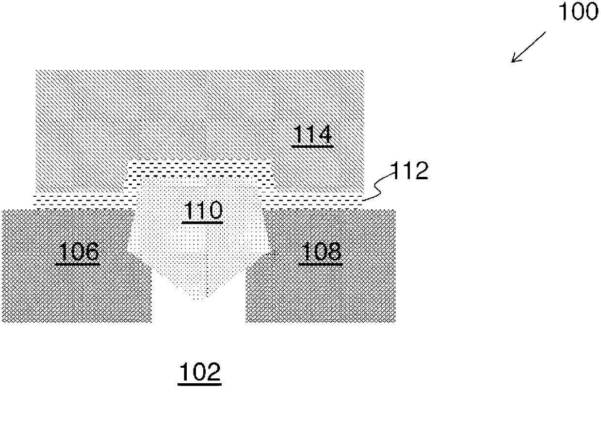
[0057] figure 1 A cross-sectional view of a FinFET with a mantle-shaped active region according to an embodiment is shown. FinFET 100 is formed over substrate 102 . FinFET 100 includes an active regi...


PUM


Abstract

A FinFET comprises an isolation region formed in a substrate, a cloak-shaped active region formed over the substrate, wherein the cloak-shaped active region has an upper portion protruding above a top surface of the isolation region. In addition, the FinFET comprises a gate electrode wrapping the channel of the cloak-shaped active region. The invention further discloses an apparatus and method for FINFET.

Description

technical field [0001] The present invention relates to the field of semiconductor technology, and more particularly, to devices and methods for FinFETs. Background technique [0002] The semiconductor industry has developed rapidly due to the continuous improvement of the integration density of various electronic components (ie: transistors, diodes, resistors, capacitors, etc.). To a large extent, the increase in integration density is due to the continuous reduction of the minimum feature size, so that more components can be integrated in a given area. However, smaller component sizes may result in more leakage current. Recently, the demand for smaller electronic devices has increased, and thus there is a need to reduce the leakage current of semiconductor devices. [0003] In a complementary metal-oxide-semiconductor (CMOS) field-effect transistor (FET), the active region includes a drain, a source, a channel region connected between the drain and source, and a channel ...

Claims


Application Information

Patent Timeline
IPC IPC(8): H01L29/78H01L29/06H01L21/336
CPCH01L29/66795H01L21/02532H01L21/0262H01L21/02631H01L21/02634H01L21/30625H01L21/3065H01L21/76224H01L27/0886H01L29/7853
Inventor 李宜静林佑儒万政典吴政宪柯志欣
Owner TAIWAN SEMICON MFG CO LTD
Why Eureka
Try Eureka