Selective cloaking circuit for use in radio frequency identification and method of cloaking RFID tags

a radio frequency identification and circuit technology, applied in the field of cloaking circuits, can solve problems such as the inability of the reader to communicate with the tag

Inactive Publication Date: 2005-12-08
SMARTRAC TECH FLETCHER INC
View PDF2 Cites 5 Cited by
  • Summary
  • Abstract
  • Description
  • Claims
  • Application Information

AI Technical Summary

Benefits of technology

[0009] The invention is defined as an improvement in a cloaked RFID tag having an antenna comprising a switch and a logic circuit coupled to the switch. The logic circuit or gate selectively allows communication of signals through the antenna during normal operation to t

Problems solved by technology

Unfortunately, this means that while the chip is in the Cloak st

Method used


Image

  • Selective cloaking circuit for use in radio frequency identification and method of cloaking RFID tags
  • Selective cloaking circuit for use in radio frequency identification and method of cloaking RFID tags

Examples


Embodiment Construction

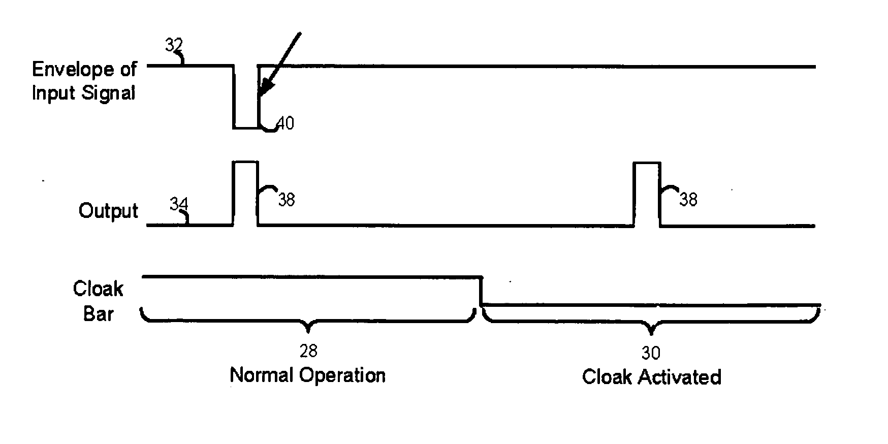
[0016] In the present invention the chip's output is disabled so that the chip cannot respond even though it is receiving information from the reader. The advantage of such a scheme is that a command can be introduced such that the Cloak state could be overcome allowing the tag 10 to respond during the Cloak period. The normal command waking the chip is still used such that any tag 10 in the Cloak state would still not be detected.

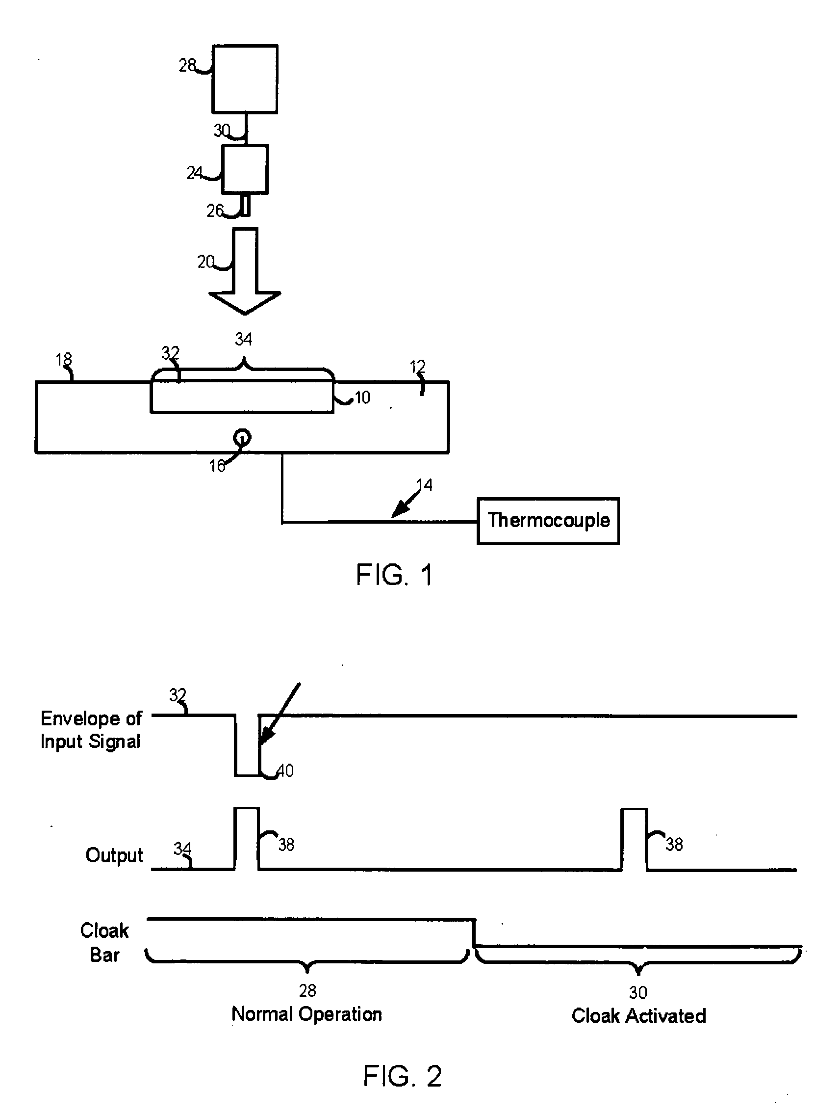
[0017] Before discussing this improvement, first consider some foundational background information concerning the operation of a cloaked RFID tag 10 in general. Cloaking a circuit or RFID tag 10 effectively disconnects the tag's antenna 42 from the rest of the tag 10. This effective disconnection is done by means of circuits on the RFID tag 10 that are designed to: (1) form a series switch between the antenna terminals and the logic circuitry of a chip comprising the tag 10; and (2) provide a meais to maintain the switch in an open or antenna-disconnected...


PUM


Abstract

The output to the antenna of an RFID tag or label is disconnected from the balance of the RFID chip by means of a series switch activated in response to a logic command, CLOAK, generated by the RFID chip. Activation of the switch disconnects the output to the antenna of the RFID tag without disconnecting its input. The output to the antenna is thus disconnected for a time sufficient to allow the remaining RFID tags in an RF interrogation field to be identified. However, the input of the antenna remains connected and is capable of receiving at any time, including during the cloaking period commands which can lift the tag out of cloaking and allow it to then selectively output its signal.

Description

[0001] This application claims priority as a continuation application under 35 U.S.C. §120 to U.S. Utility patent application Ser. No. 09 / 768,327 entitled, “A SELECTIVE CLOAKING CIRCUIT FOR USE IN A RADIOFREQUENCY IDENTIFICATION AND METHOD OF CLOAKING RFID TAGS”, filed on Jan. 23, 2001, which is incorporated herein by reference in its entirety.BACKGROUND OF THE INVENTION [0002] 1. Field of the Invention [0003] The invention relates to radio frequency identification tags or labels and in particular to a cloaking circuit used to assist in the read operations of RFID transponders. [0004] 2. Description of the Prior Art [0005] In U.S. Pat. No. 5,963,144, incorporated herein by reference, what is described is an antenna of an RFID tag or label which is disconnected from the balance of the RFID chip by means of a series switch activated in response to a logic command, CLOAK, generated by the RFID chip. Activation of the switch disconnects the antenna of the RFID tag from the remainder of ...

Claims


Application Information

Patent Timeline
IPC IPC(8): G06K7/00G06K19/07H04B1/59
CPCG06K7/0008G06K19/0723G06K7/10029
Inventor DALGLISH, DAVE G.
Owner SMARTRAC TECH FLETCHER INC
Why Eureka
Try Eureka