Infusion device and driving mechanism and process for same with actuator for multiple infusion uses

a technology of infusion device and driving mechanism, which is applied in the direction of dynamo-electric components, piston pumps, dynamo-electric machines, etc., can solve the problems of increased risk of adverse effects, increased risk of leaching or other interactions of materials, and adverse effects on the patient to whom the infusion medium is administered, so as to prolong the operation life of the drive mechanism and efficient power use

Inactive Publication Date: 2005-08-23
MEDTRONIC MIMIMED INC
View PDF35 Cites 597 Cited by
  • Summary
  • Abstract
  • Description
  • Claims
  • Application Information

AI Technical Summary

Benefits of technology

[0012]Further embodiments of the invention relate to such devices and drive mechanisms configured for implantation in a patient's body and, thus, configured to have a relatively small thickness dimension, for example, to minimize trauma to the implant recipient (referred to herein as the patient). However, aspects of the invention may apply to external infusion devices and drive mechanisms for such external devices and, thus, other embodiments of the invention relate to such external infusion devices and drive mechanisms.
[0019]As described in further detail below, armature portions of actuators employed in embodiments of the present invention may be configured with a reduced diameter, for example, to reduce fluidic resistance to actuator movement. Alternatively, or in addition, further embodiments of the present invention employ an armature structure that is free of apertures (or employs a reduced number of apertures as compared to actuators described in U.S. patent application Ser. No. 10 / 033,722) and, thus, may be provided with a protective layer or coating in a simplified manufacturing process.
[0021]Alternatively, or in addition, actuators according to further embodiments of the invention employ a piston portion that has a central channel and valve structure for increasing the flow rate of infusion medium into a pumping chamber and inhibiting backflow of infusion medium from the pumping chamber. In yet further embodiments, the diameter of the piston portion may be reduced and / or the diameter of the piston channel in which the piston moves may be increased, to increase the flow rate of infusion medium into the pumping chamber. By accommodating an increased flow rate, the drive mechanisms may be operable with a greater variety of infusion media.
[0023]In addition, a number of features described herein and in U.S. patent application Ser. No. 10 / 033,722 can provide, or be combined to contribute to, the efficient use of power to, prolong the operational life of the drive mechanism.

Problems solved by technology

In such infusion devices, the chemical interaction of the infusion medium with materials used for such components may have an adverse effect on the patient to which the infusion medium is administered.
The risk of such an adverse effect may be greater for implantable infusion devices, where components of an infusion pump may remain in contact with infusion medium over a prolonged period of time inside of an implanted device.
For example, contact with the armature may cause leaching or other interactions of materials between the infusion medium and the armature.
Such interactions may adversely alter the medical effect of the infusion medium on the patient.
Prolonged contact may cause other detrimental effects, such as corrosion of the armature.
However, if the particular type of infusion medium is not known at the time of manufacture of the pump mechanism, for example, in the case in which a pump mechanism is being manufactured for multiple possible infusion uses, the ability to study effects on all possible infusion media may not be practical or possible.

Method used


Image

  • Infusion device and driving mechanism and process for same with actuator for multiple infusion uses
  • Infusion device and driving mechanism and process for same with actuator for multiple infusion uses
  • Infusion device and driving mechanism and process for same with actuator for multiple infusion uses

Examples


Embodiment Construction

[0050]The following detailed description is of the best presently contemplated mode of implementing the invention. This description is not to be taken in a limiting sense, but is made merely for the purpose of illustrating the general principles of embodiments of the invention. The scope of the invention is best defined by the appended claims.

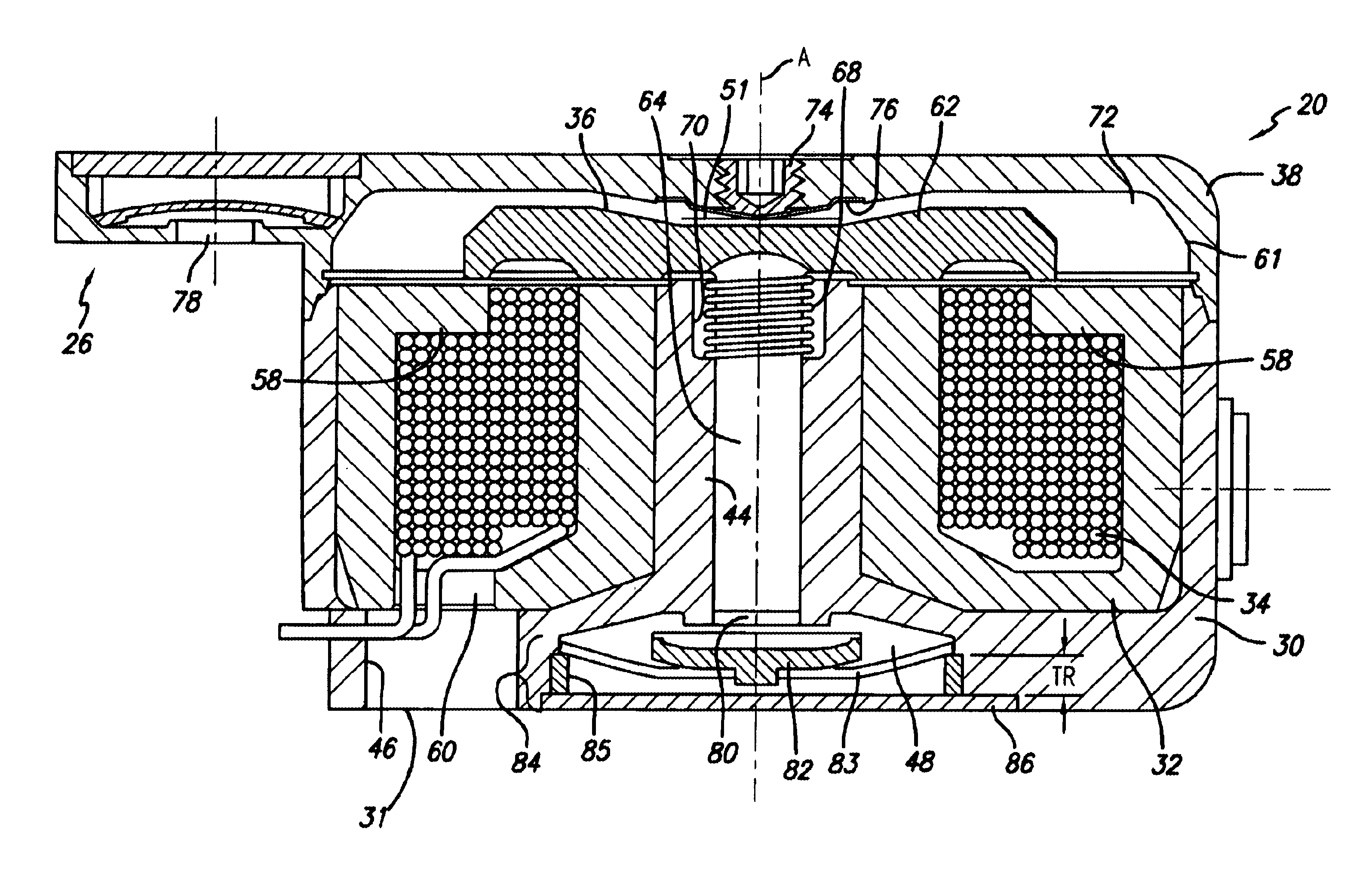
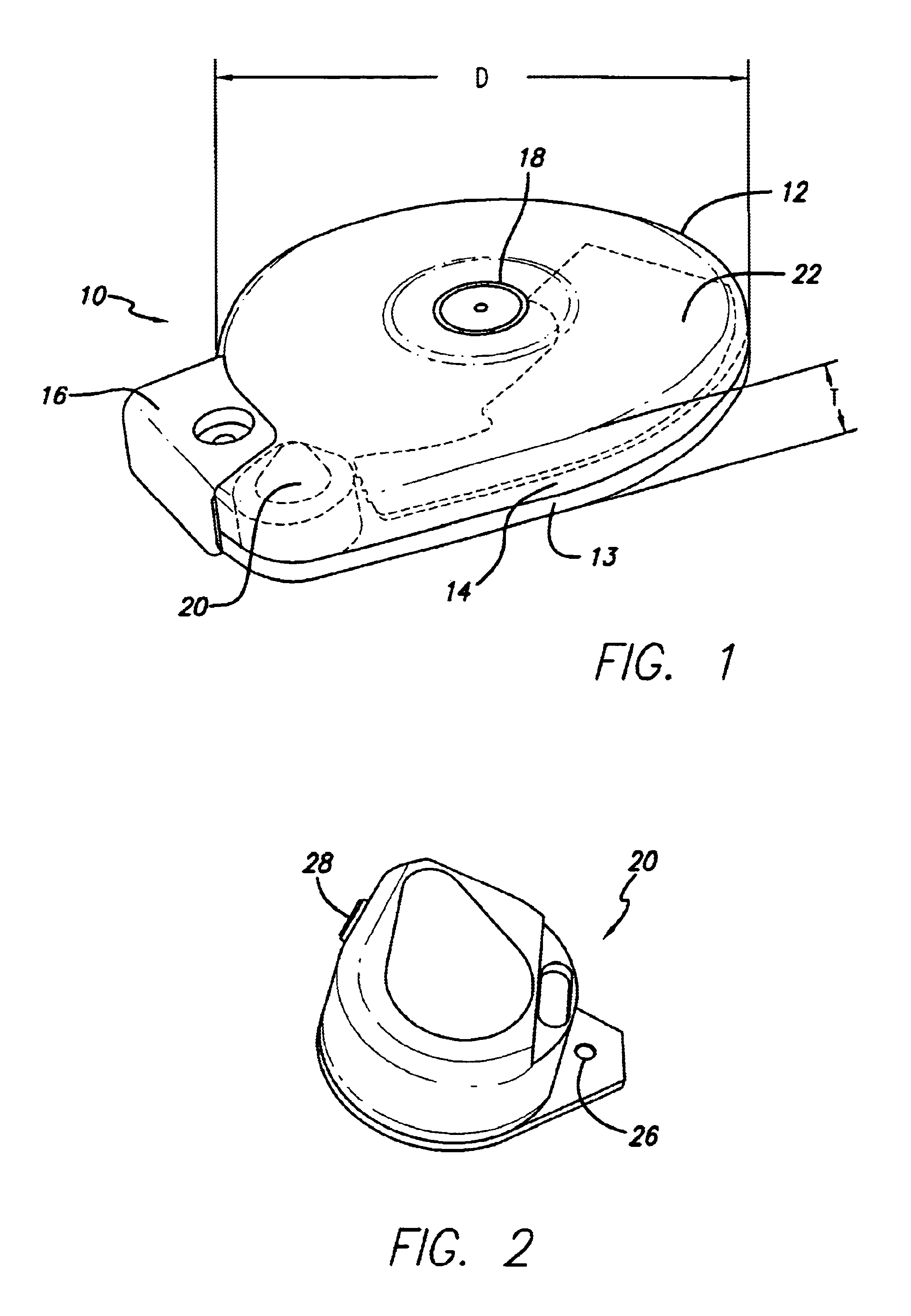
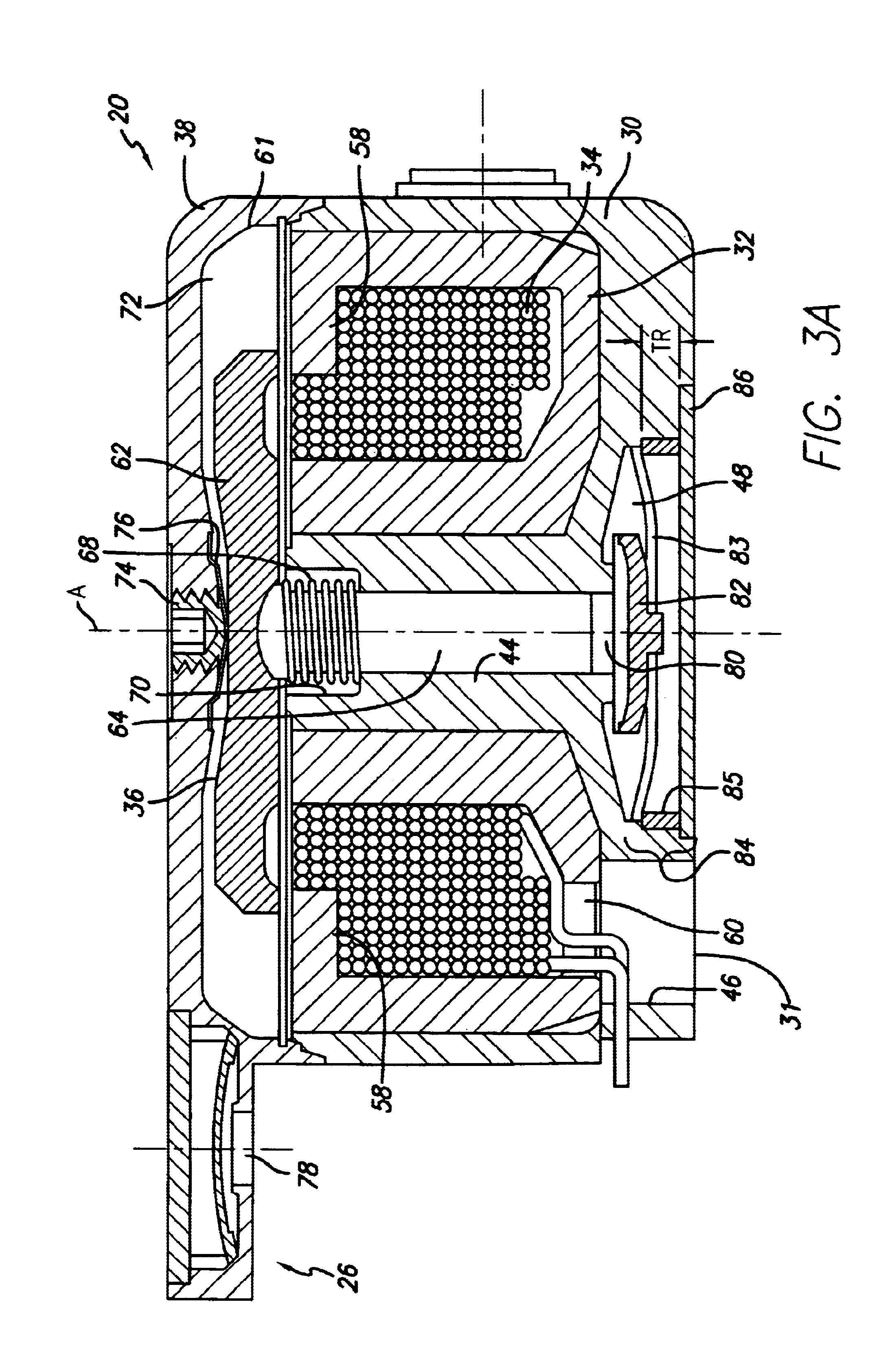
[0051]As discussed above, the present invention relates generally to infusion devices having drive mechanisms and also to drive mechanism configurations for infusion of a medium into a patient or other environment. Embodiments of the invention relate to such devices and drive mechanisms configured for use with any one of multiple different infusion media.

[0052]Embodiments of the invention relate to such devices and drive mechanisms configured for implantation in a patient's body. Embodiments described herein allow the drive mechanism for such infusion device to have a relatively small thickness dimension, for example, to minimize trauma to the ...


PUM


Abstract

A drive mechanism for delivery of infusion medium a coil capable of being electrically activated to provide an electromagnetic field. The coil surrounds a piston channel extending in an axial direction. An armature is located adjacent the coil, on one side of the axial channel. The armature is moveable toward a forward position, in response to the electromagnetic field produced by activation of the coil. A piston is located within the piston channel and is moveable axially within the channel to a forward position, in response to movement of the armature to its forward position. The armature and piston are moved toward a retracted position, when the coil is not energized. The armature may be configured with a reduced diameter by including a coil cup for supporting the coil including a shelf portion defining at least a portion of a pole surface of the coil cup.

Description

CROSS REFERENCE TO RELATED APPLICATIONS[0001]Embodiments of the present invention relate to a U.S. patent application entitled “Infusion Device and Driving Mechanism For Same,” Ser. No. 10 / 033,722, filed Dec. 27, 2001, the disclosure of which is incorporated by reference herein.FIELD OF THE INVENTION[0002]The present invention relates generally to infusion devices, systems and processes and, in particular embodiments to infusion devices, systems and processes employing a drive mechanism configuration having an actuator configured for improved efficient operation with a variety of types of infusion media. Further embodiments of the invention relate to drive mechanisms for such infusion devices and systems, and processes of making and using such drive mechanisms.BACKGROUND[0003]Infusion devices are typically used to deliver infusion media, such as medication, to patients. An implantable infusion device is medium to the patient at a regulated dosage. An external infusion device is desi...

Claims


Application Information

Patent Timeline
Patent Type & Authority Patents(United States)
IPC IPC(8): F04B17/04
CPCA61M5/14216A61M5/14276F04B17/042F04B17/046F04B35/045
Inventor GRAY, JOHNBOSLEY, ROBERT W.LORENZEN, ERIC
Owner MEDTRONIC MIMIMED INC
Why Eureka
Try Eureka