Printed circuit board arrangement comprising an oscillatory system

a technology of printed circuit board and oscillatory system, which is applied in the association of printed circuit non-printed electric components, electrical apparatus casings/cabinets/drawers, instruments, etc., can solve problems such as the inability to receive detection results from sensors, and achieve the effect of small thickness dimension

Active Publication Date: 2016-06-07
ROBERT BOSCH GMBH
View PDF8 Cites 0 Cited by
  • Summary
  • Abstract
  • Description
  • Claims
  • Application Information

AI Technical Summary

Benefits of technology

[0005]Preferably, the elastically formed element is additionally formed so as to be damping, and also form internal damping during the oscillation. In this way, a spring-mass system with an oscillation damper can advantageously be formed.
[0013]In a preferred embodiment, the surface region is decoupled from oscillations, in particular flexural oscillations, of a surface of the printed circuit board next to the surface region, the printed circuit board comprising a recess for the surface region and the surface region being arranged in the recess. For example, the surface region is decoupled and thus separated from the surface region surrounding the surface region by means of slits, in particular sawed slits. The decoupling may, for example, be generated by means of a saw or by means of laser cutting. By means of the decoupling formed in this way, the surface region can oscillate freely on the elastic element relative to the surface region surrounding the surface region of the printed circuit board.
[0014]Preferably, the surface region is connected to the surface of the printed circuit board, in particular the printed circuit board surface surrounding it, by means of a film, in particular a cover film. Preferably, the film has a smaller thickness dimension than the printed circuit board. The intermediate space, in particular a gap, between the printed circuit board and the oscillatory surface region of the printed circuit board, can thus advantageously be sealed. By virtue of the sealing, advantageously no contamination can enter the intermediate space between the printed circuit boards. The film is, for example, coated with adhesive on at least one side. Such a film, in particular self-adhesive film, may also advantageously close the gap, formed for the decoupling, between the surface region and the printed circuit board surface surrounding it, after the printed circuit board has been fitted with components and also after the electronic components have been soldered to the printed circuit board.
[0016]In another embodiment, the elastically formed element comprises a plastic foam, in particular a polyurethane foam. By virtue of the plastic foam, the elastic element can advantageously be provided economically.
[0018]In a preferred embodiment, the element is arranged between the planes formed by the printed circuit board and the other printed circuit board. In this way, the surface region with the printed circuit board surrounding it can advantageously be arranged in the same plane. By virtue of the decoupling by means of the elastic element, in a multilayer printed circuit board assembly no more installation space in the height direction is used up by constructing a spring-mass system.

Problems solved by technology

In the case of printed circuit boards known from the prior art, which are equipped with electronic components, for example with sensors, the problem has been identified that the printed circuit boards together with the components arranged thereon may be excited in natural oscillations which can impair a detection result to be received by the sensor.
This problem arises, for example, in the case of sensors which are formed as oscillation receivers, for example in the case of microphones, pressure sensors or acceleration sensors.
Furthermore, the problem may consist in an oscillation frequency of the printed circuit board lying in a detection frequency range of the sensor, and thus leading to a detection result which is not in causal relationship with the measurement quantity to be detected.

Method used


Image

  • Printed circuit board arrangement comprising an oscillatory system
  • Printed circuit board arrangement comprising an oscillatory system
  • Printed circuit board arrangement comprising an oscillatory system

Examples


Embodiment Construction

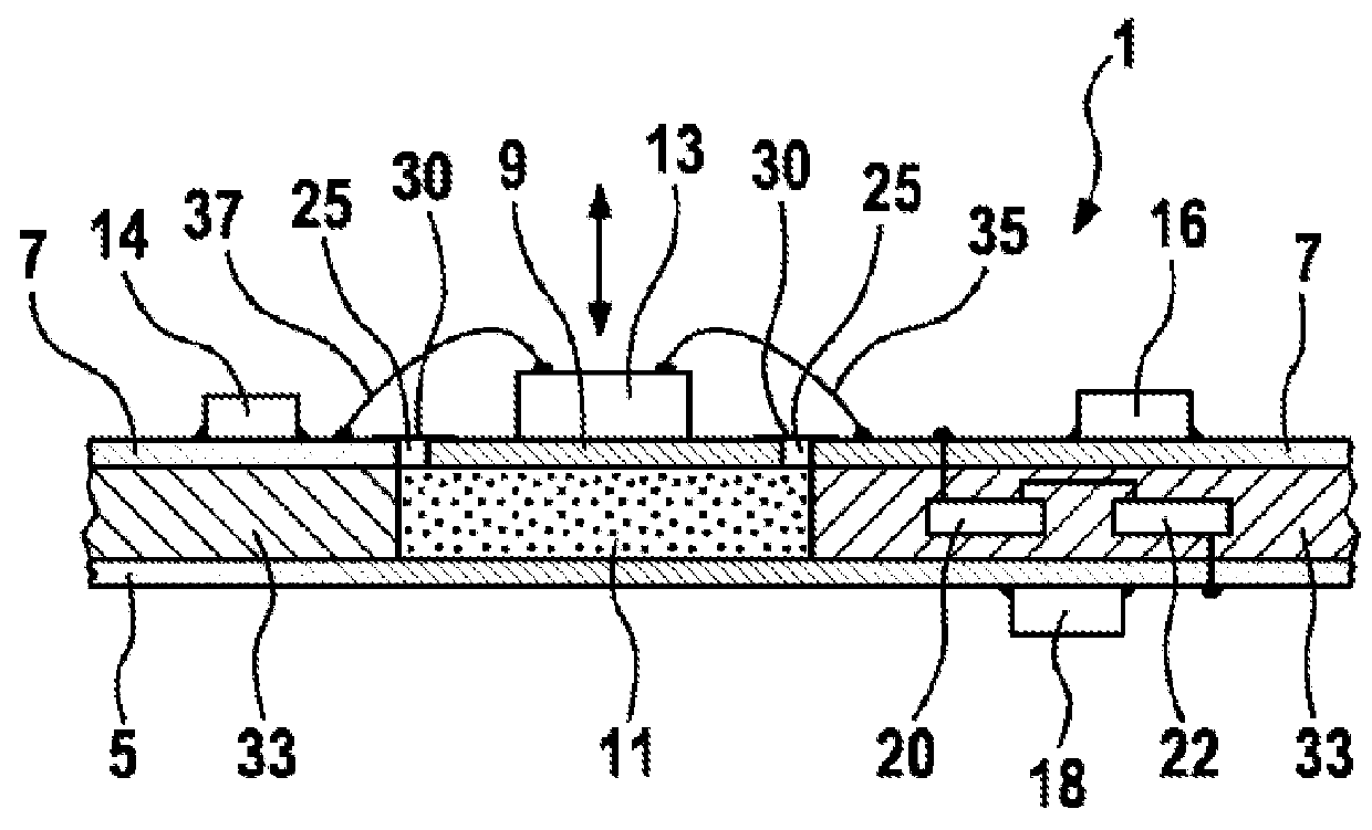
[0028]FIG. 1 shows an exemplary embodiment of a printed circuit board arrangement 1. The printed circuit board arrangement 1 comprises a printed circuit board 5 and a printed circuit board 7 connected to the printed circuit board 5. The printed circuit boards 5 and 7 are arranged mutually parallel, an interlayer 33 which connects the printed circuit boards 5 and 7 to one another being arranged at least locally between the printed circuit boards 5 and 7. The printed circuit boards 5 and 7 are for example fiber-reinforced, in particular glass fiber-reinforced epoxy resin printed circuit boards. In this exemplary embodiment, the printed circuit board arrangement 1 forms a multilayer printed circuit board, the printed circuit boards 5 and 7 respectively forming a layer which enclose the interlayer 33, also referred to as an inner layer, between them. For example, the interlayer 33 is formed by an epoxy resin layer. The printed circuit boards 5 and 7 each have a copper sheet on at least ...


PUM

PropertyMeasurementUnit
edge lengthaaaaaaaaaa
thicknessaaaaaaaaaa

Abstract

The invention relates to a printed circuit board arrangement, more particularly a multilayer printed circuit board. The printed circuit board arrangement comprises at least two printed circuit boards which are arranged parallel to one another and connected to one another. According to the invention, in the case of the printed circuit board arrangement of the type mentioned initially, at least one surface region of one printed circuit board is connected to another printed circuit board of the printed circuit board arrangement by means of an element embodied in an elastic and / or damping fashion in such a way that an oscillatory system, more particularly a spring-mass system, an oscillatory bending strip or a flexurally oscillatory board is formed by means of the surface region of the printed circuit board and the element.

Description

BACKGROUND OF THE INVENTION[0001]The invention relates to a printed circuit board arrangement, in particular a multilayer printed circuit board. The printed circuit board arrangement comprises at least two printed circuit boards arranged mutually parallel and connected to one another.[0002]In the case of printed circuit boards known from the prior art, which are equipped with electronic components, for example with sensors, the problem has been identified that the printed circuit boards together with the components arranged thereon may be excited in natural oscillations which can impair a detection result to be received by the sensor. This problem arises, for example, in the case of sensors which are formed as oscillation receivers, for example in the case of microphones, pressure sensors or acceleration sensors. Furthermore, the problem may consist in an oscillation frequency of the printed circuit board lying in a detection frequency range of the sensor, and thus leading to a dete...

Claims


Application Information

Patent Timeline
Patent Type & Authority Patents(United States)
IPC IPC(8): H05K1/11G01L19/06H05K5/00H05K1/14H05K1/02G01P15/08G01P15/125H05K1/18G01P15/09H05K3/46H05K3/00
CPCH05K1/148G01L19/06G01P15/0802H05K1/14H05K1/141H05K1/142H05K1/144H05K5/0056G01P15/09G01P15/125G01P2015/0882H05K1/0271H05K1/145H05K3/0064H05K3/4611H05K2201/0133H05K2201/041H05K2201/09063H05K2201/09081H05K2201/10083H05K2201/10151
Inventor HANSEN, UWE
Owner ROBERT BOSCH GMBH
Why Eureka
Try Eureka