Collision test apparatus, vehicle design method, and vehicle

一种碰撞测试、设计方法的技术,应用在车辆的测试、车辆冲击测试、机器/结构部件的测试等方向,能够解决能力低等问题

Inactive Publication Date: 2013-09-11
TOYOTA JIDOSHA KK
View PDF9 Cites 18 Cited by
  • Summary
  • Abstract
  • Description
  • Claims
  • Application Information

AI Technical Summary

Problems solved by technology

However, traditional crash test equipment has a low ability to reproduce actual crashes

Method used


Image

  • Collision test apparatus, vehicle design method, and vehicle
  • Collision test apparatus, vehicle design method, and vehicle
  • Collision test apparatus, vehicle design method, and vehicle

Examples


Embodiment Construction

[0026] Now, preferred embodiments of the crash test apparatus according to the present invention will be described in detail below with reference to the accompanying drawings.

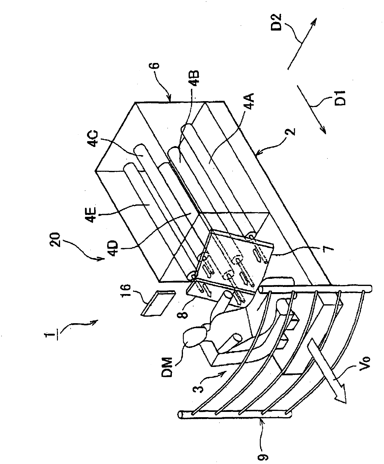
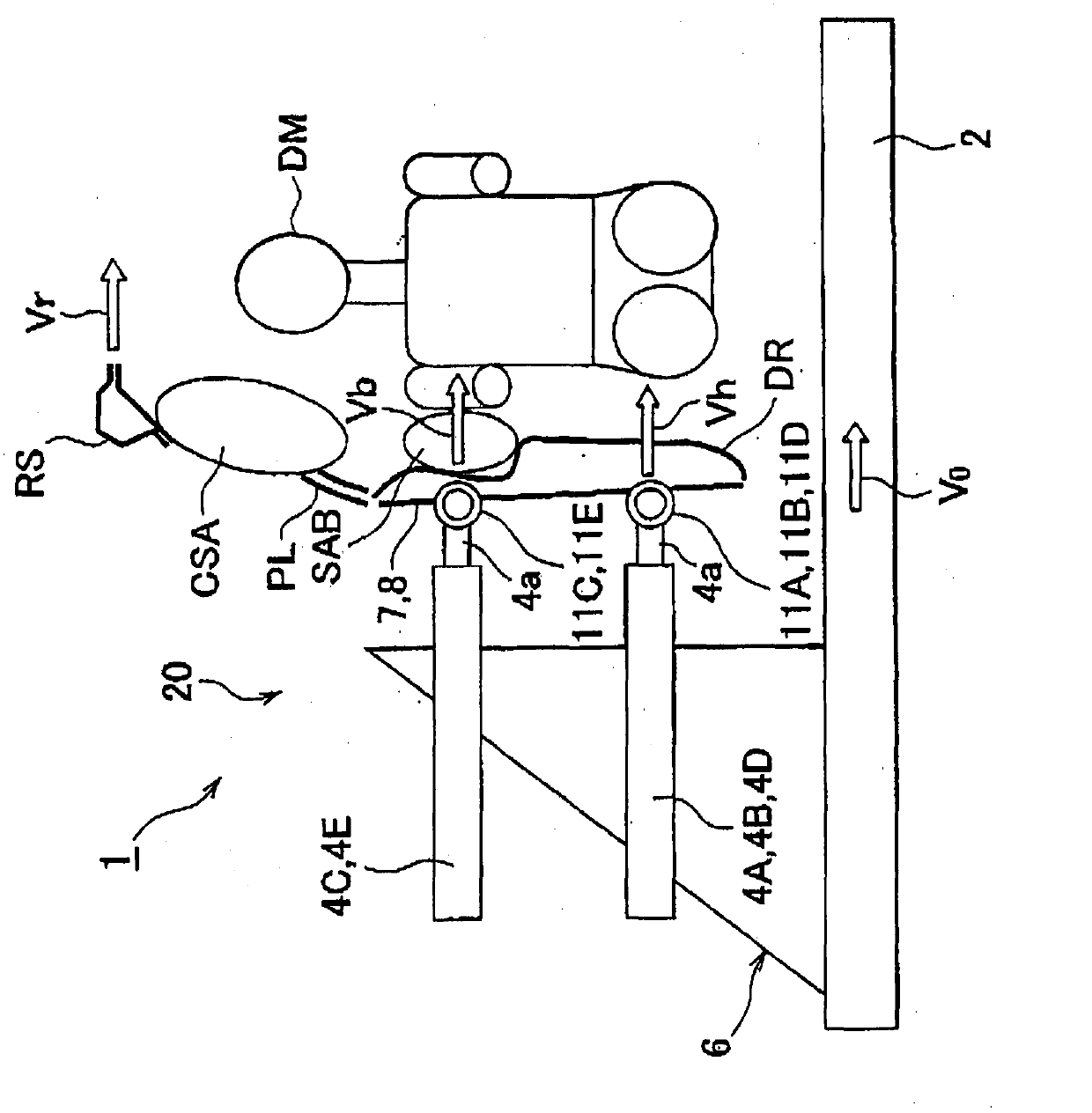
[0027] The crash test apparatus 1 is capable of performing a crash test by simulating a vehicle crash. As an example of collision, figure 1 The crash test device 1 shown in simulates a side crash in which an oncoming vehicle collides with the damaged vehicle from the side. Such as figure 1 As shown in , the crash test device 1 includes: a sliding trolley 2; a carrying unit 3 on which a dummy DM is carried; actuators 4A, 4B, 4C, 4E; actuator support units 6; Simulated fixture (fixed unit) 7 ; column simulated fixture (fixed unit) 8 ; and dummy protective net 9 .

[0028] A collision can be simulated using the crash test apparatus 1 by setting the dummy DM and the vehicle structural components during the test, and causing the vehicle structural components to collide with the dummy DM. Such as figur...


PUM


Abstract

A collision test apparatus (1) includes actuators (4A, 4B, 4C, 4D, 4E) that move a vehicle structural member toward the side of a carrying unit (3) on which a dummy DM is carried. The actuators (4A, 4B, 4C, 4D, 4E) can be driven independently of each other. Therefore, the actuators (4A, 4B, 4C, 4D, 4E) move the vehicle structural member at respectively different driving speeds. In other words, the collision test apparatus (1) does not simply move the vehicle structural member such that the vehicle structural member collides with the dummy, but also causes the vehicle structural member to collide with the dummy DM while moving the vehicle structural member at different speeds in different positions.

Description

technical field [0001] The present invention relates to a crash test device, a vehicle design method and a vehicle. Background technique [0002] For example, a conventional crash test apparatus is disclosed in Japanese Patent Application Laid-Open No. 07-215246 (JP-A-07-215246). The crash test apparatus includes: a target block on which a dummy and a door structure of a vehicle are arranged; and a plug block which inputs a load to the door structure. The seat carrying the dummy and the door structure adjacent the outside of the seat are arranged on the target carriage. During the test, the plug carriage moves towards the target carriage and collides with the door structure. The door structure activates the airbag and collides with the dummy. [0003] When performing a collision test by simulating a vehicle collision, it is necessary to reproduce a state close to an actual collision. However, conventional crash test equipment has a low ability to reproduce actual crashes...

Claims


Application Information

Patent Timeline
Patent Type & Authority Applications(China)
IPC IPC(8): G01M17/007
CPCG01M17/0078
Inventor 小林功藤原泰介胜又俊一
Owner TOYOTA JIDOSHA KK
Why Eureka
Try Eureka