Detergent pouring controller

A detergent injection and controller technology, which is applied to washing devices, tableware washing machines/rinsing and washing machine parts, and other washing machines, etc., can solve problems such as inaccurate injection accuracy, complex structure, and blocked equipment operation, and achieve compact structure , simple structure and simple assembly

Active Publication Date: 2013-09-18
HANGZHOU KAMBAYASHI ELECTRONICS
View PDF9 Cites 10 Cited by
  • Summary
  • Abstract
  • Description
  • Claims
  • Application Information

AI Technical Summary

Problems solved by technology

[0010] The present invention aims to solve the problems that the structure of the liquid detergent dispensing device configured in the current washing equipment is relatively complicated, the dispensing accuracy is not accurate enough, and the operation of the equipment is hindered due to the easy residual solidification of detergent, etc., and a detergent dispensing controller of the present invention is provided for this purpose. The detergent dosing controller is simple in structure, small in size, easy to install and use, the detergent in the equipment is not easy to remain, and the dosing accuracy is high

Method used


Image

  • Detergent pouring controller
  • Detergent pouring controller
  • Detergent pouring controller

Examples


Embodiment 1

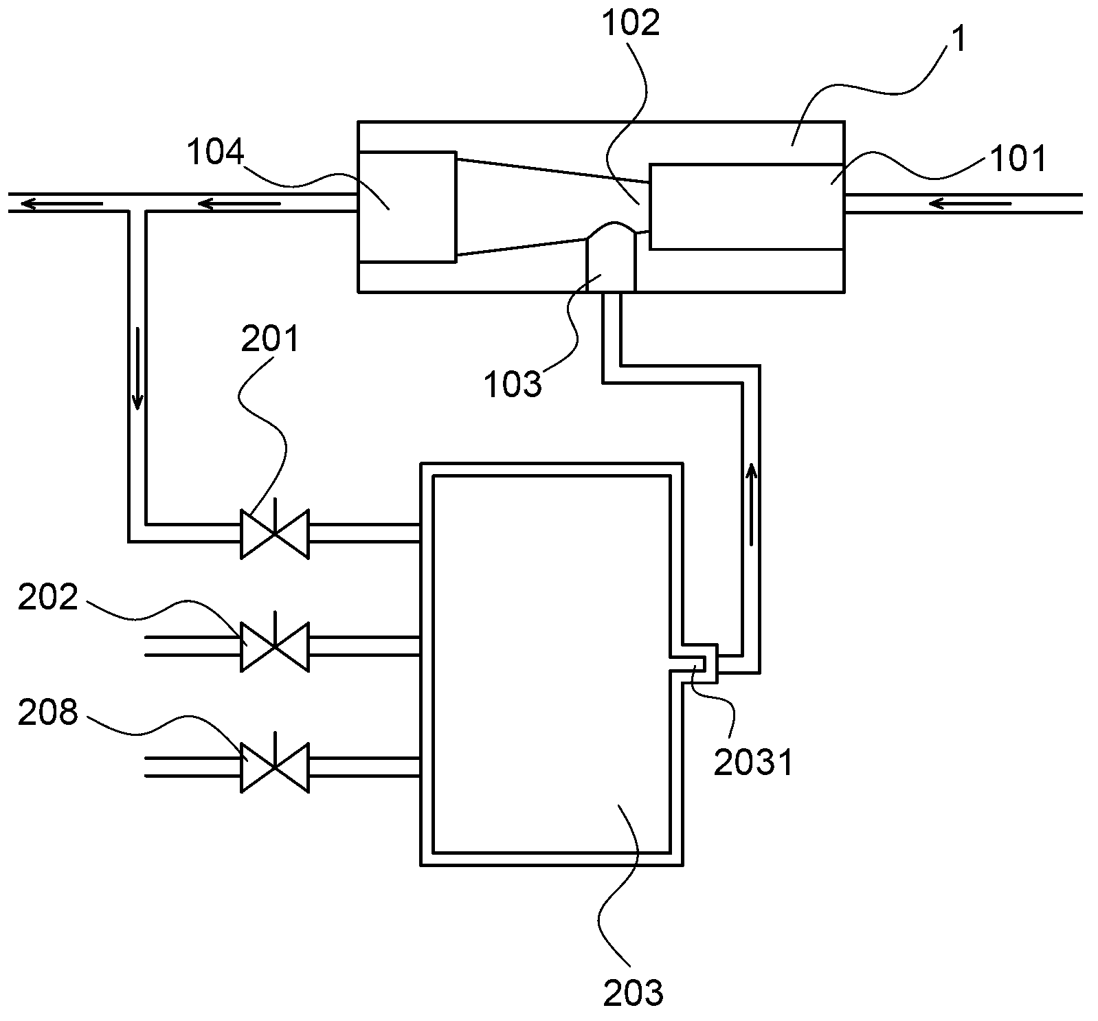
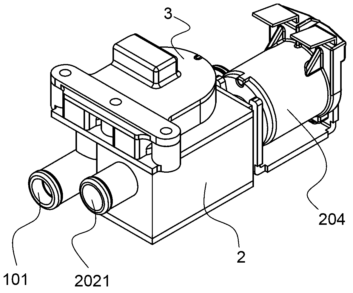
[0032]The detergent injection controller is provided with a valve body 2, the valve body has a valve cavity 203, the valve cavity has a valve cavity outlet 2031, the valve body is provided with a valve A201 and a valve B202, and the valve A and the valve B are opened. The outlet of the valve A and The outlet of valve B passes through the valve cavity 203; the valve body is connected with a negative pressure generator 1, which has an inlet 101 connected to the water source and an outlet 104 connected to the water inlet pipe of the washing tub. There is a zoom port 102 connected, the small port of the zoom port corresponds to the inlet, the large port of the zoom port corresponds to the outlet, the side of the zoom port is connected with a negative pressure port 103, and the outlet of the negative pressure generator is connected with the inlet 2011 of valve A, The negative pressure port of the negative pressure generator is in communication with the outlet of the valve chamber, a...

Embodiment 2

[0034] In this example, a valve C is provided in the valve body described in Example 1. When the valve C is open, the outlet of the valve C passes through the valve chamber, and the valve C has an inlet connected to the detergent B liquid storage tank. Other structures are the same as in Example 1.

Embodiment 3

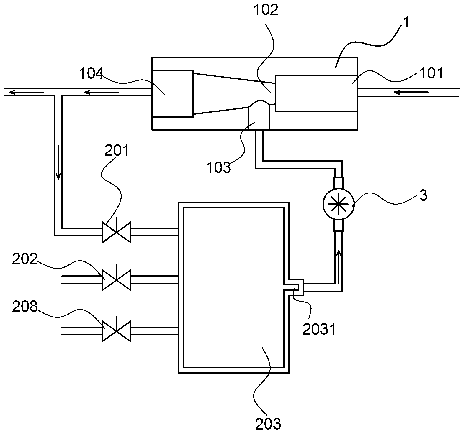
[0036] In this example, a bonnet 207 is connected to the valve cavity described in Example 1, and a negative pressure port 2072 and a communication port 2071 are provided on the bonnet, and the negative pressure port and the negative pressure port of the negative pressure generator Connected, the communication port communicates with the outlet of the valve cavity, and a flow sensor 3 is connected between the communication port and the negative pressure port. Other structures are the same as in Example 1.


PUM


Abstract

The invention discloses a detergent pouring controller which is simple in structure, accurate in pouring and difficult in scaling by residues. The controller comprises a valve A (201), a valve B (202), a valve cavity (203) and a negative pressure generator (1), wherein the valve cavity is provided with a valve cavity outlet (2031); the outlets of the valve A and the valve B are communicated with the valve cavity; the negative pressure generator is provided with an inlet (101) connected with a water source and an outlet (104) connected with a washing barrel water inlet pipe, and a scaling port (102) is connected between the inlet and the outlet, the small end of the scaling port (102) corresponds to the inlet and the large end thereof corresponds to the outlet; a negative pressure port (103) is communicated with the side part of the scaling port; the outlet of the negative pressure generator is communicated with the inlet of the valve A, and the negative pressure port thereof is communicated with the valve cavity outlet; the inlet of the valve B is the outlet communicated with a detergent A liquid storage tank. The controller is used for pouring of the detergent.

Description

technical field [0001] The invention relates to a device for dispensing liquid preparations, in particular to a liquid washing dispensing control device equipped on electric washing machines such as electric washing machines and electric dishwashers. Background technique [0002] In the past, the liquid detergent (or softener, softener, sterilizing solution, etc.) of electric washing equipment such as electric washing machines and electric dishwashers using liquid detergent was added by the user to store the liquid detergent to be injected in advance. Inside the container, the washing equipment flushes them into the washing bucket through water flushing or other mechanical methods according to the washing process. In this method, the dosage of detergent depends on the arbitrariness of the user's operation, and detergent needs to be added to the container during each washing process. With the continuous advancement of detergent liquefaction, it is an application trend to sto...

Claims


Application Information

Patent Timeline
Patent Type & Authority Applications(China)
IPC IPC(8): D06F39/02A47L15/44
Inventor 王华鲍鹏飞
Owner HANGZHOU KAMBAYASHI ELECTRONICS
Why Eureka
Try Eureka