Supercharge Your Innovation With Domain-Expert AI Agents!

crankshaft trencher

A trench digger and crankshaft technology, which is applied in the direction of earth mover/shovel, construction, etc., can solve the problems of high equipment cost, low efficiency, unreliable performance, etc., and achieve low construction equipment cost, reliable performance and high efficiency. Effect

Inactive Publication Date: 2015-09-30
温州广达建设有限公司
View PDF7 Cites 0 Cited by
  • Summary
  • Abstract
  • Description
  • Claims
  • Application Information

AI Technical Summary

Problems solved by technology

[0002] At present, the trenchers used to dig trenches in construction projects have the disadvantages of low efficiency, high cost of construction equipment, and unreliable performance.

Method used


Image

  • crankshaft trencher
  • crankshaft trencher
  • crankshaft trencher

Examples


Embodiment Construction

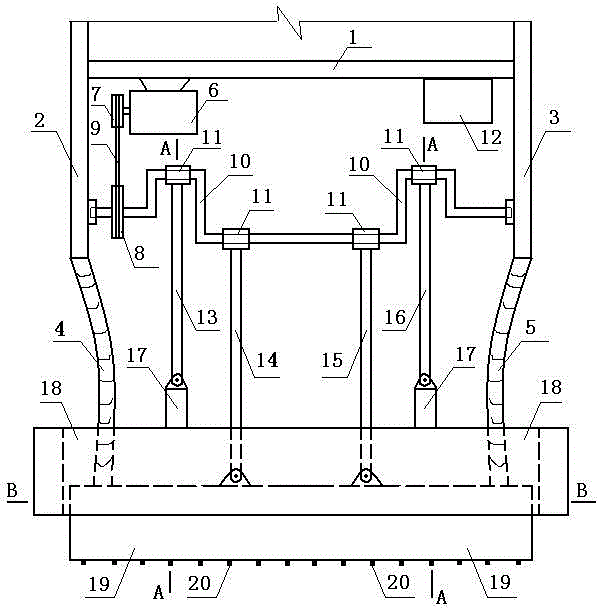
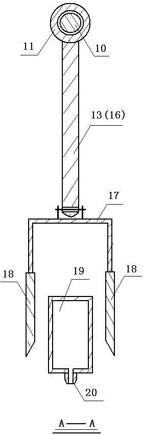
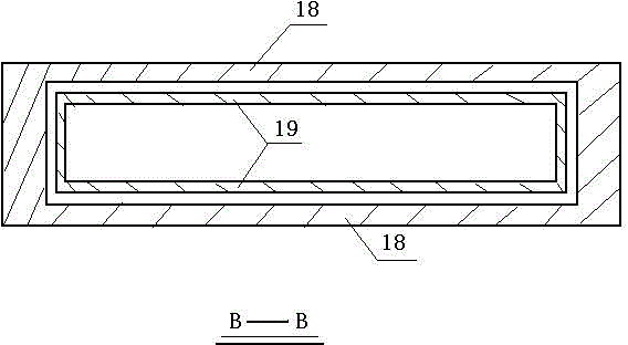
[0013] Accompanying drawing is a kind of specific embodiment of the present invention, and this embodiment is provided with side rod A2 on the left side, and side rod B3 is provided on the right side, and the lower end of side rod A is connected with flexible pipe A4, and the lower end of flexible pipe A is connected with the left end of impact block B19, and The lower end of the rod B is connected to the hose B5, and the lower end of the hose B is connected to the right end of the impact block B; the connecting beam 1 connects the side rod A and the side rod B, the driving machine is arranged under the connecting beam, and the driving shaft of the driving machine is provided with a driving wheel 7 , the driving wheel is connected to the driven wheel 8 through the V-belt 9, the driven wheel is arranged at the left end of the crankshaft 10, the crankshaft is provided with four shaft joints, each shaft joint is provided with a shaft sleeve 11, and the left shaft sleeve is hinged t...


PUM


Abstract

A crankshaft trencher adopts the structure that a side rod A and a side rod B are arranged on the left aide and the right side respectively, a hose A is connected to the lower end of the side rod A, the lower end of the hose A is connected to the left end of an impact block B, a hose B is connected to the lower end of the side rod B, the lower end of the hose B is connected to the right end of an impact block B, the side rod A and the side rod B are connected through a connecting beam, a driving machine is arranged below the connecting beam, a driving axle of the driving machine is provided with a driving wheel connected to a driven wheel through a V belt, the driven wheel is arranged at the left end of a crankshaft provided with four bosses, each boss is provided with a shaft sleeve, the left-side shaft sleeve is hinged to a left-side U-shaped connector through a connecting rod A, the right-side shaft sleeve is hinged to a right-side U-shaped connector through a connecting rod D, the two middle shaft sleeves are hinged to the impact block B through a connecting rod B and a connecting rod C, and nozzles are arranged at the lower end of the impact block B.

Description

technical field [0001] The invention relates to a trencher, in particular to a crankshaft trencher used for digging trenches in construction engineering. Background technique [0002] At present, the trenchers used to dig trenches in construction projects all have the disadvantages of low efficiency, high cost of construction equipment, and unreliable performance. Contents of the invention [0003] The present invention fills up the gap above and provides a crankshaft trencher. [0004] The present invention is achieved through the following technical solutions: [0005] A crankshaft trenching machine, with a side rod A on the left and a side rod B on the right, a hose A is connected to the lower end of the side rod A, the lower end of the hose A is connected to the left end of the impact block B, and a hose B is connected to the lower end of the side rod B , the lower end of the hose B is connected to the right end of the impact block B; the connecting rod connects the ...

Claims


Application Information

Patent Timeline
Patent Type & Authority Patents(China)
IPC IPC(8): E02F5/02
Inventor 陈其广
Owner 温州广达建设有限公司
Features
  • R&D
  • Intellectual Property
  • Life Sciences
  • Materials
  • Tech Scout
  • Unparalleled Data Quality
  • Higher Quality Content
  • 60% Fewer Hallucinations
Learn More