
Tubing Hanger Stabilization Device

A tubing hanger and hanger technology, applied in the direction of drill pipe, casing, wellbore/well parts, etc., can solve the problems of unavoidable accidents, broken seal rings, hanger seal rings, etc., to achieve Significant economic and social benefits, avoiding rework, and ensuring successful construction

Inactive Publication Date: 2016-06-29
CHINA PETROLEUM & CHEM CORP +1
View PDF6 Cites 0 Cited by
  • Summary
  • Abstract
  • Description
  • Claims
  • Application Information

AI Technical Summary

Problems solved by technology

The hanger must pass through the blowout preventer during the lowering process. Due to the inclination of the derrick, the hanger cannot be lowered straightly, and the ram in the blowout preventer often hangs and damages the sealing ring on the hanger.
In order to solve the problem that the sealing ring of the hanger is broken during the lowering process, the oil pipe connected to the hanger is pushed by manpower from one side of the deflection to the other on site. The device is in the center, and the operator must look down close to the wellhead to observe, so as not to avoid sudden accidents, there are potential safety hazards

Method used


Image

  • Tubing Hanger Stabilization Device
  • Tubing Hanger Stabilization Device

Examples


Embodiment Construction

[0010] Embodiments of the present invention will be described below in conjunction with the accompanying drawings.

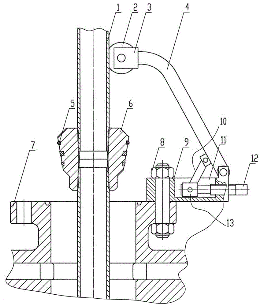
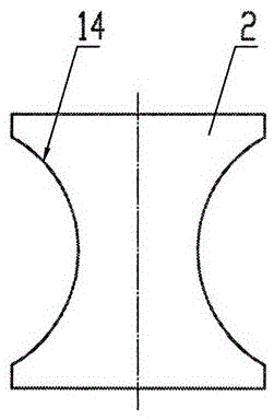
[0011] As can be seen from the figure, the embodiment of the present invention includes a lifting oil pipe 1, a roller 2, a wheel frame 3, a bracket 4, a sealing ring 5, a hanger 6, a blowout preventer 7, a connecting bolt 8, a base 9, a support rod 10, and an adjusting screw 11. The support seat 13, the sealing ring 5 is installed on the hanger 6, the lower part of the lifting oil pipe 1 is connected with the hanger 6, the oil pipe in the well is connected under the hanger 6 and passes through the blowout preventer 7, the base 9 is fixed by the connecting bolt 8 On the blowout preventer 7, the track groove 11 is arranged on the base 9, and there is a screw hole on the right side of the base 9. Enter the track groove 11 after the hole passes, the support seat 13 is sleeved on the left end of the adjusting screw rod 12, the support seat 13 is in the track groove ...


PUM


Abstract

The invention provides an oil tube suspender centering device, wherein a seal ring is installed on a suspender, the lower part of a lifting oil tube is connected with the suspender, the lower part of the suspender is connected with an oil tube in a well, a base is fixed on a blowout preventer through a connection bolt, a railway slot is formed in the base, a screw hole is formed in the right side surface of the base, an internal screw thread of the screw hole is matched with an external screw thread of a regulation screw rod, the regulation screw rod enters the railway slot after passing through the screw hole in the right side surface of the base, a support seat is mounted at the left end of the regulation screw rod in a sleeving way, the support seat is in the railway slot, the lower end of a support rod is connected with the support seat in a hinged manner, the upper end of the support rod is connected with the lower part of a bracket in a hinged manner, the lower end of the bracket is connected with the base in a hinged manner, a wheel carrier is installed at the upper part of the bracket and is provided with an idler wheel, the idler wheel is close to the outer side of the lifting oil tube, the regulation screw rod is rotated to push the lifting oil tube to enable the lifting oil tube to be in the middle of the interior of the blowout preventer, the seal ring on the suspender is not broken through suspending, the suspender can be centered by rotating the regulation screw rod, an operator does not need to get close to a wellhead, and the operation is safe.

Description

technical field [0001] The invention relates to equipment used for lowering a tubing hanger in oilfield operations, in particular to a centralizing device for a tubing hanger. Background technique [0002] When operating oil and water wells in the oil field, a hanger must be lowered to hang the tubing in the well on the large cross of the wellhead device. The hanger also plays the role of sealing the oil casing so that the high-pressure liquid above the hanger cannot leak into the casing, so , there is a sealing ring on the hanger. The hanger has to pass through the blowout preventer during the lowering process. Due to the inclination of the derrick, the hanger cannot be lowered straightly, and the ram in the blowout preventer often hangs and damages the sealing ring on the hanger. In order to solve the problem that the sealing ring of the hanger is broken during the lowering process, the oil pipe connected to the hanger is pushed by manpower from one side of the deflection...

Claims


Application Information

Patent Timeline
Patent Type & Authority Patents(China)
IPC IPC(8): E21B33/03E21B17/10
Inventor 张兴瑞邵宝华许建华张莹李佳罗志文梁磊林振敏
Owner CHINA PETROLEUM & CHEM CORP
Learn More